 David Scholten
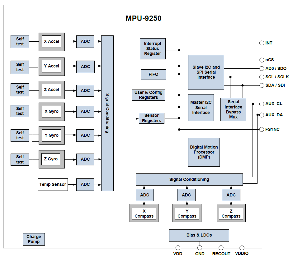
During the initial investigation and choosing of the PCB assembly service (Seeed Fusion), I found a “9-axis” all-in-one Inertial Measurement Unit (IMU) that was part of the company’s library of surface mount parts (MPU-9250). This unit, seen below, has a 3-axis gyro, 3-axis accelerometer, “3-axis” compass and temperature sensor. The complexity and functionality of this tiny chip is mind boggling, but it has been made very simple to use thanks to a 100/400kHz I²C interface and a few auxiliary µcontroller I/O connections.
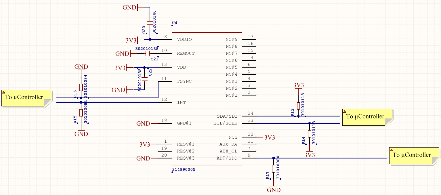
From a hardware standpoint it is very simple to implement this chip as the datasheet provides more than an adequate explanation of how to wire it up:
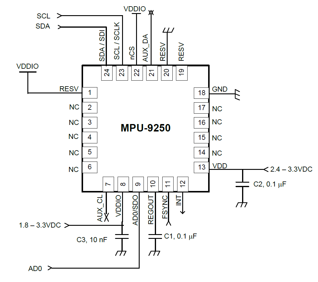
So long as the correct capacitors are used for its bypassing and power requirements (X7R ceramics), there will be no problems!
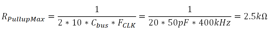
The only challenge is to select the pullup resistors for the I²C serial lines, which need to operate at a clock rate of 400kHz. The datasheet lists the input capacitance as “<10pF”, but with the µcontroller connected, the PCB layout and some margin for error, we’ll say the capacitance is 50pF. A 400kHz clock waveform has a total period of 2.5µs and a 1.25µs half period (i.e. one pulse). If we assume the desired rise time to be about a 10th of this, we need a rise time of about 125ns. Let’s make the time constant of the pullup resistor and bus capacitance equal to half of this (62.5ns), which means an 86% rise (i.e. 0V to 2.85V for a 3.3V bus) in 125ns. With a bus capacitance of 50pF and a time constant of 62.5ns, the maximum pullup resistance is 2.5kΩ. For added safety, a resistance of 2kΩ was selected.
Discussions
Become a Hackaday.io Member
Create an account to leave a comment. Already have an account? Log In.