0%
0%
FreqCounter
A high-precision, I2C-connected & configurable frequency/event counter good to 50+ MHz with 1Hz +/- 1 precision.
Become a Hackaday.io member
Already have an account? Log in.
Just one more thing
To make the experience fit your profile, pick a username and tell us what interests you.
Pick an awesome username
hackaday.io/
Your profile's URL: hackaday.io/username. Max 25 alphanumeric characters.
Pick a few interests
Projects that share your interests
People that share your interests

 hIOTron
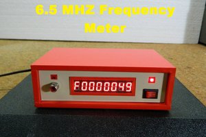
 mircemk
 edensrock
 Capt. Flatus O'Flaherty ☠
Any more progress on this frequency counter? It sounds like a nice design...