deʃhipu
-
Fabrication
01/24/2018 at 19:36 • 1 commentI just got some photos from the Makerfabs showing how the fabricated devices came out:
![]()
There is just a small glitch on the silkscreen on the back, but I don't care much, as this is going to be covered by the battery anyways:
---------- more ----------![]()
Apparently, the number 10 was too complex to handle — I should have simplified it.
The devices should arrive soon, and then I will make them available on Tindie. Before that, I need to finalize the first version of the libraries and the documentation for them. So much to do, so little time.
-
Bigger Battery
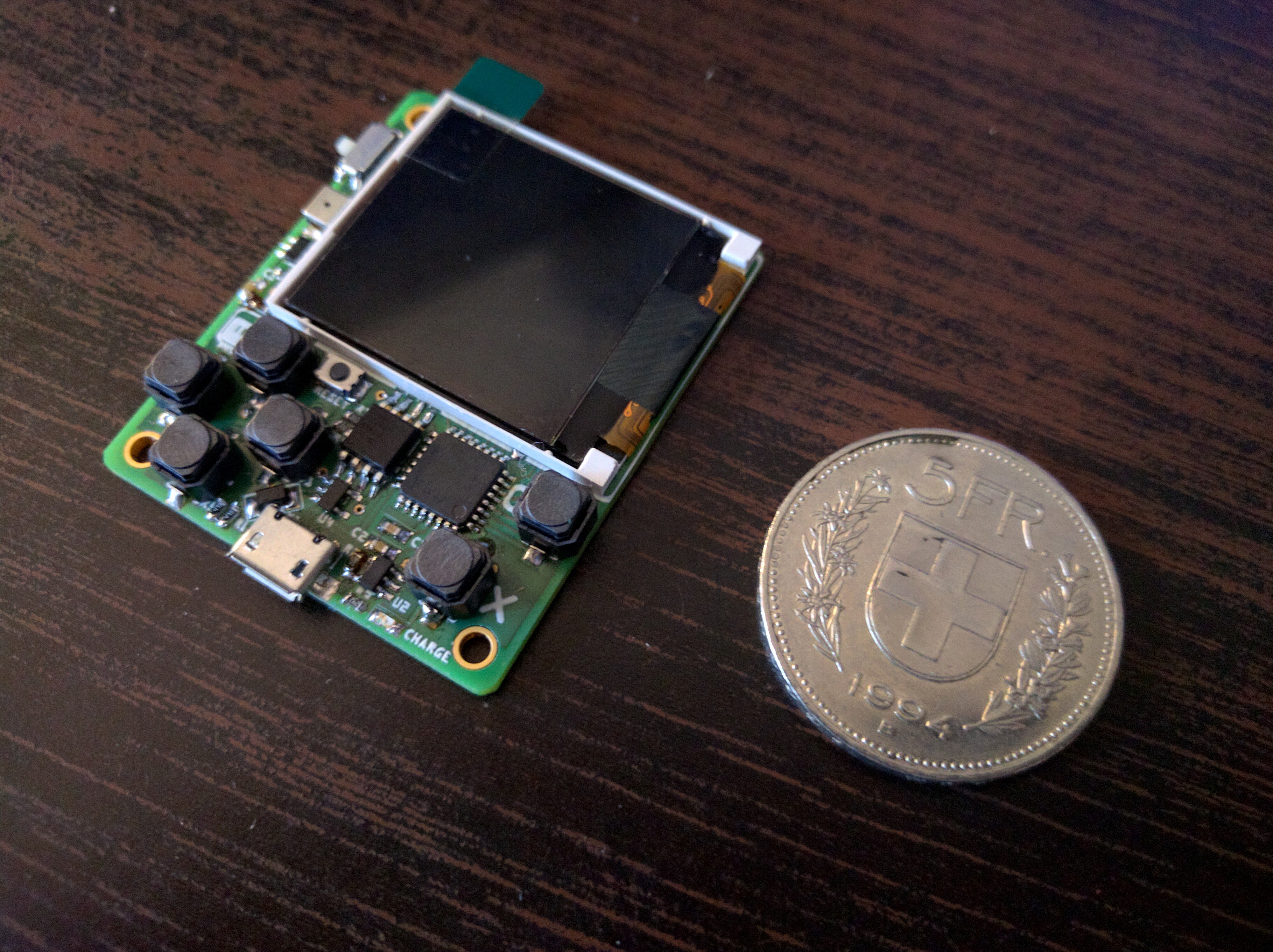
01/10/2018 at 20:12 • 6 commentsThe LIR2032 coin cell batteries that I used with this device so far are not the perfect solution. Sure, they are easy to get and replace, don't look nearly as scary as the aluminium pouch of the LiPo batteries, and actually have enough electricity to play for almost an hour, but they also have down sides: they are very slow to charge, 40 minutes of play time is not nearly enough for the more boring travels, and they don't look very well on the back of the device.
So I looked around for a different battery. I has to be:
- standard, so that I can tell users what battery they need to get,
- larger and capable of faster charging,
- easily obtainable and cheap,
- protected from over-discharge,
- flat and roughly the same size as the device,
- physically robust.
That actually narrows the possibilities considerably, but I had an idea: let's use a battery from a cellphone — not a smartphone battery, those are too big and expensive, but a battery from one of the popular dumb phones. Nokia used to be a popular brand, so I'm sure there are a lot of cheap Nokia batteries I could use!
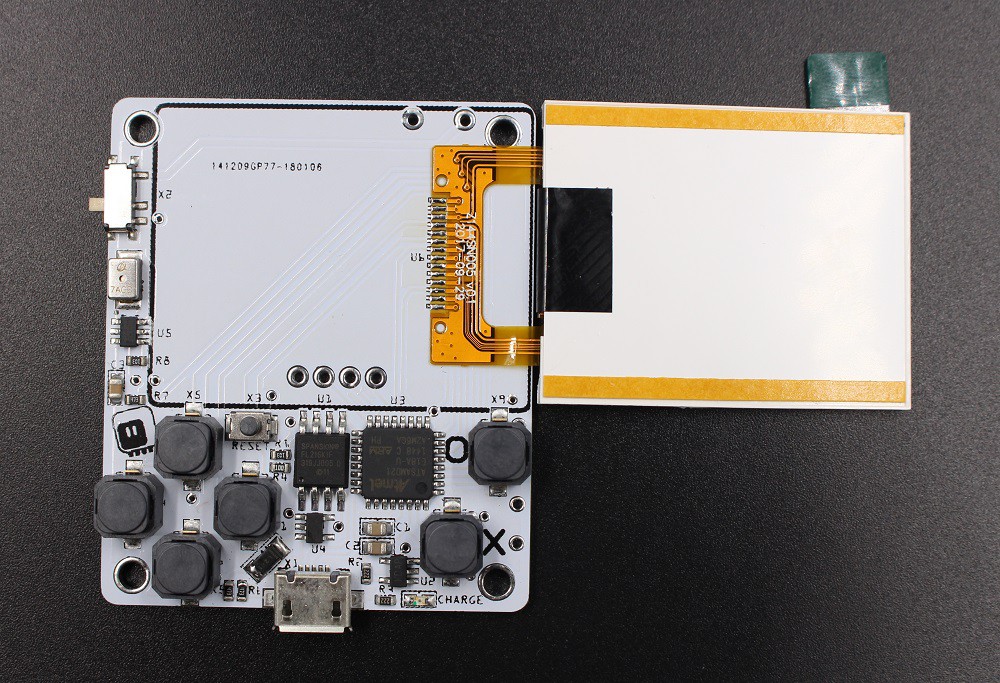
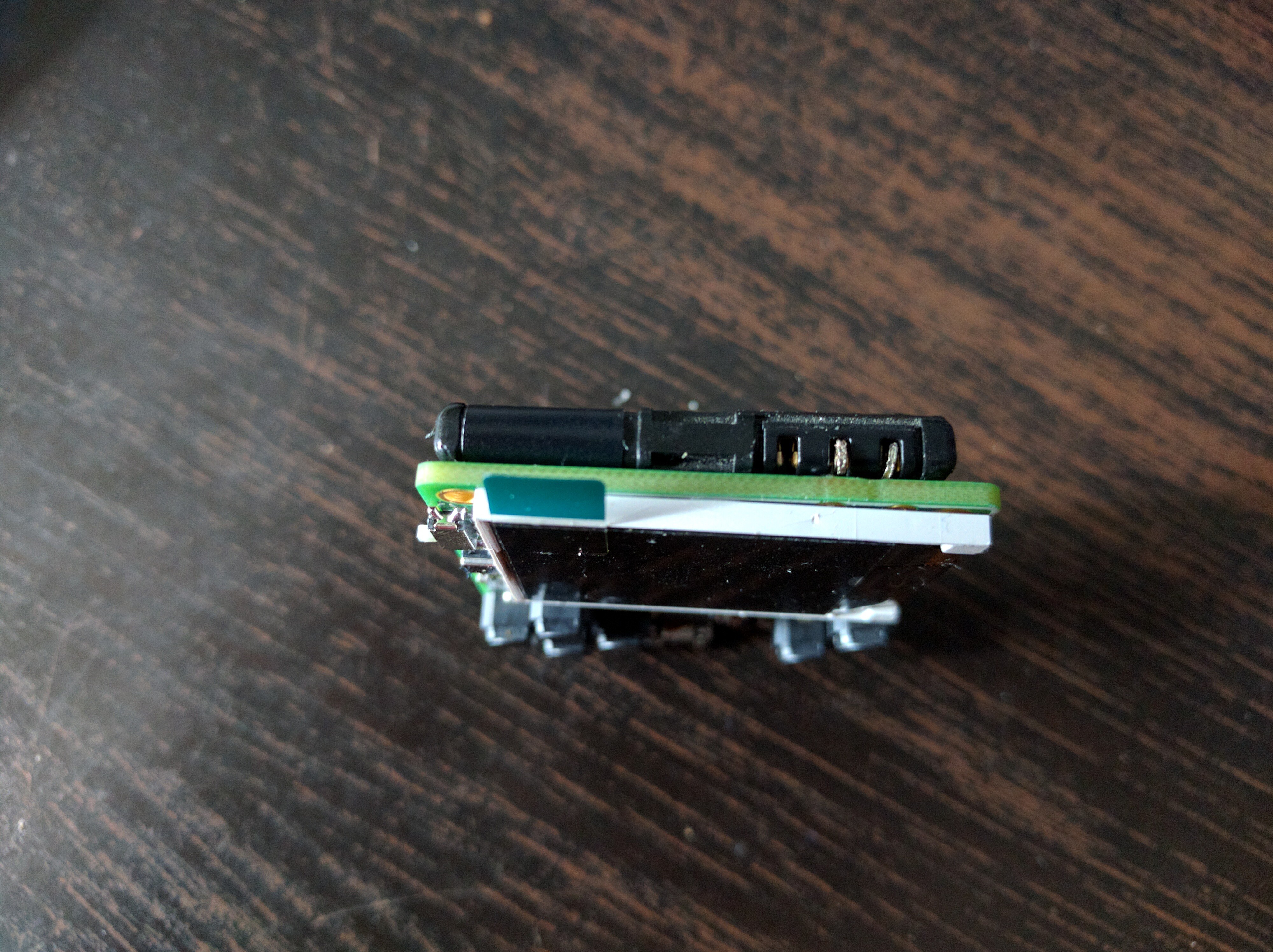
Looking around I found the "Cellphone Knowledge Base" wiki, and there I found the two battery models that fit: BL-5B and BL-4S. I ordered one of each, and they arrived recently. The bigger and older one, BL-5B, arrived first:
![]()
It's a bit of a tight fit, exactly the same height as the µGame. But the connector it uses let's me improvise something from goldpins, so it works pretty well:
![]()
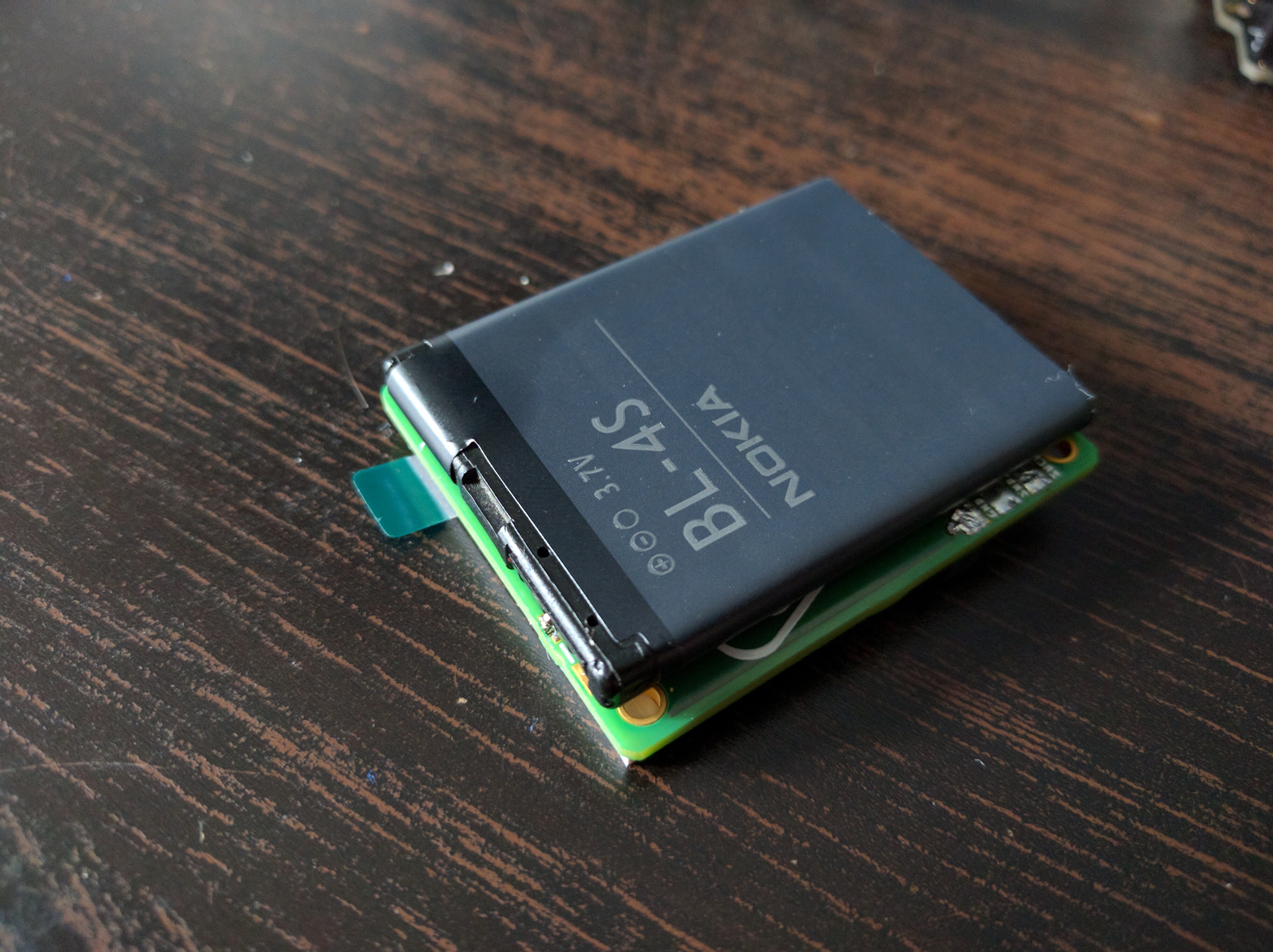
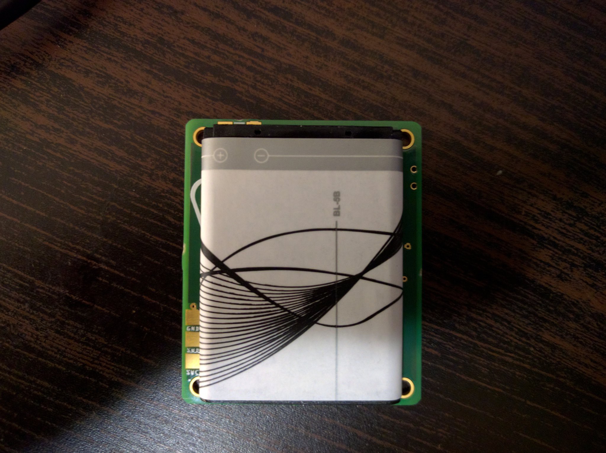
You can see the holes are not exactly right (I didn't have the dimensions when I designed the PCB) but they are close enough for this to work. Today the second battery arrived, and I actually like it a bit more. It's smaller but thicker, and it doesn't cover the mounting holes:
![]()
The connector is a bit more tricky — I think I will simply solder it to the battery pads, after attaching the battery with 2-sided tape. It's supposed to be a prototype kit anyways.
@MatejEusk is working on designing a 3D-printed case for this, it might work a little bit better with those batteries then.
-
Final Prototype
12/29/2017 at 22:54 • 1 commentThe version 8 PCBs arrived from Aisler, together with the stencil, and it looks great this time!
![]()
Please especially note the smooth edges of the board, without any trace of the panelization tabs. Of course I immediately assembled one of the boards and tested it:
![]()
It works great. Please note the much nicer alignment of the chips, and the fact that there are no parts under your fingers. One of the buttons had to be moved a little to the side, but it's actually better that way.
Of course there were still changes needed, but they are so small, that I can confidently send the gerber files to the fab without ordering one more test board. The changes included adding one more debug pad for connecting VCC, adding holes to the debug pads so that it's easier to connect probes to them, moving some of the resistors a little to make them easier to solder, and fixing the stencil to include the pads for the USB port, and exclude the holes of the power switch (workarounds for Fritzing's weirdness).
I also wrote the step-by-step testing instructions, and made a test program:
![]()
So everything is ready for fabrication. I will now send all that to the fab house, and see what they think about it.
-
nGame is µGame, only Smaller
12/28/2017 at 15:55 • 2 commentsWhile I was designing the #D1 Mini X-Pad Shield, the #PewPew FeatherWing and most recently µGame, I struggled with the same problem: how to fit the direction pads and fire buttons on as small PCB area as possible, while still keeping them usable. I think I have tested pretty much any type of SMD buttons on offer from China, tried different layouts and packing schemes, and even did some uncanny experiments with fitting larger buttons to smaller footprints. But I never quite had the courage to really push the limits. Until now, that is.
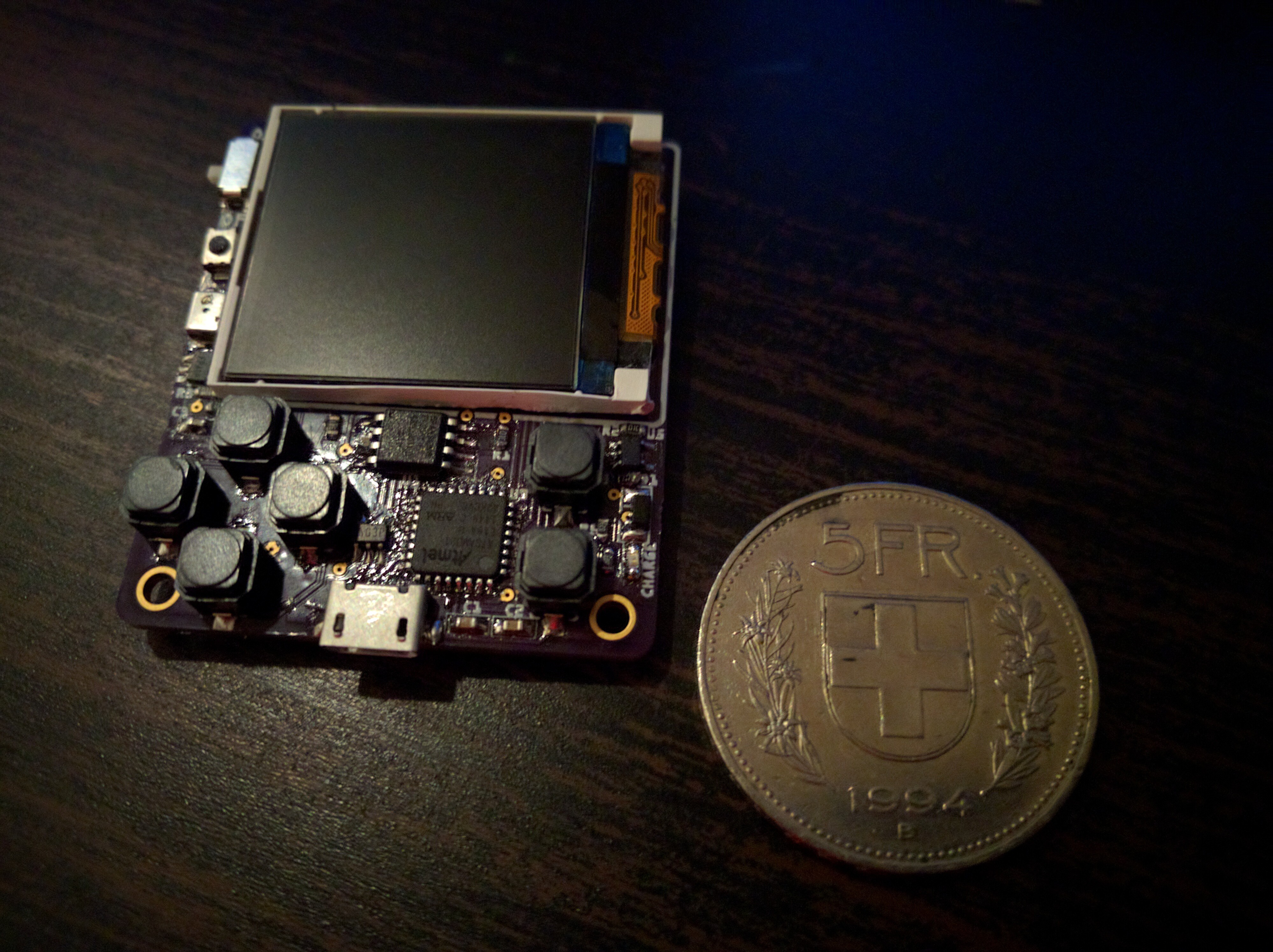
![]()
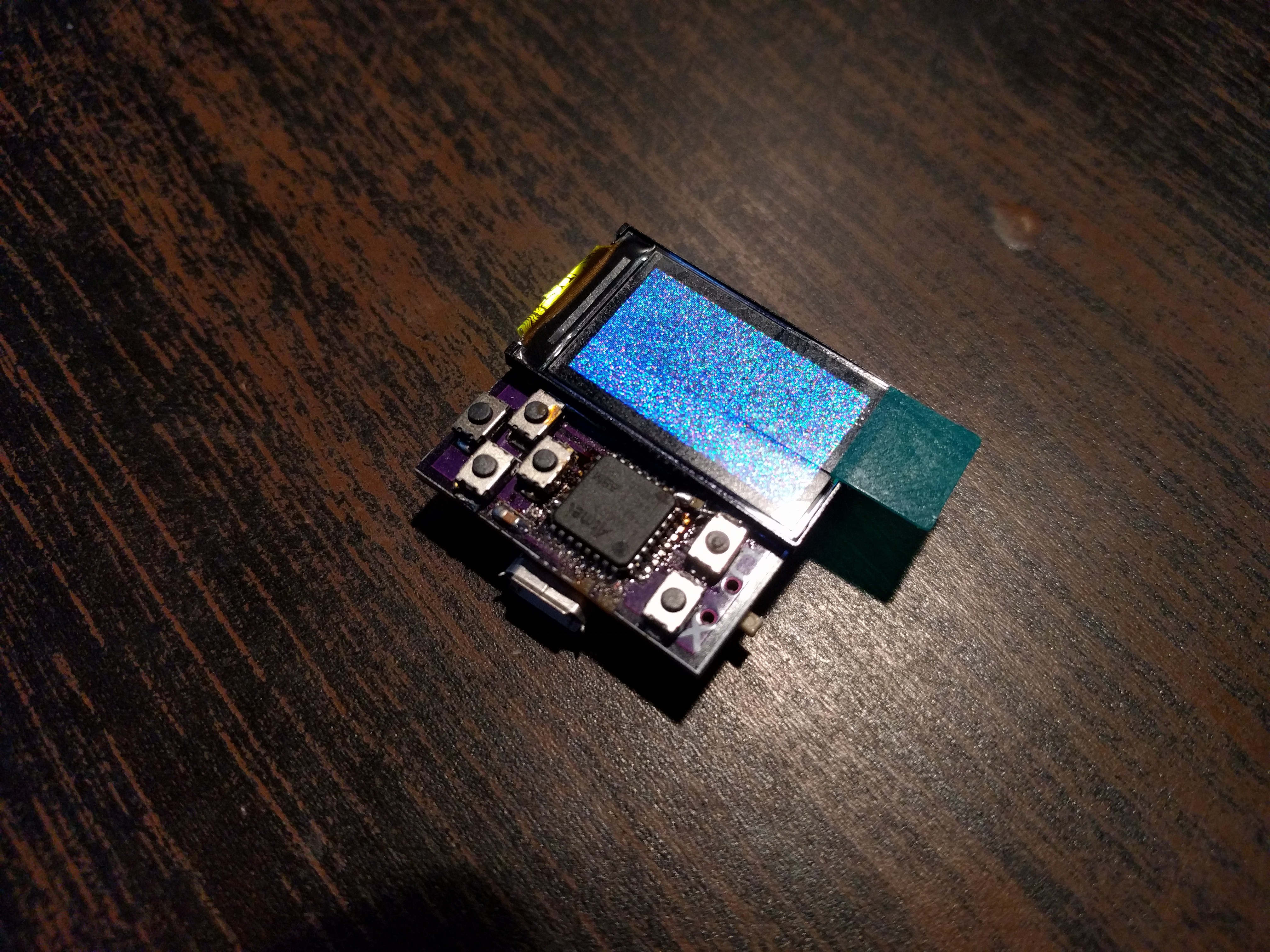
This is what happens to µGame when you leave it in your pants pocket in the dryer and let it shrink. It uses the same ST7725S display that I used in #Trinket M0 TFT — even the driver fits, you just have to adjust the screen size in it. It uses the smallest 2-pad buttons I could find — they use 1206 resistor footprints. The SAMD21 microcontroller has no additional flash storage this time, so we are very constrained in what fits there — none of the demos for µGame I had worked out of the box, that's why the photo shows just random pixels.
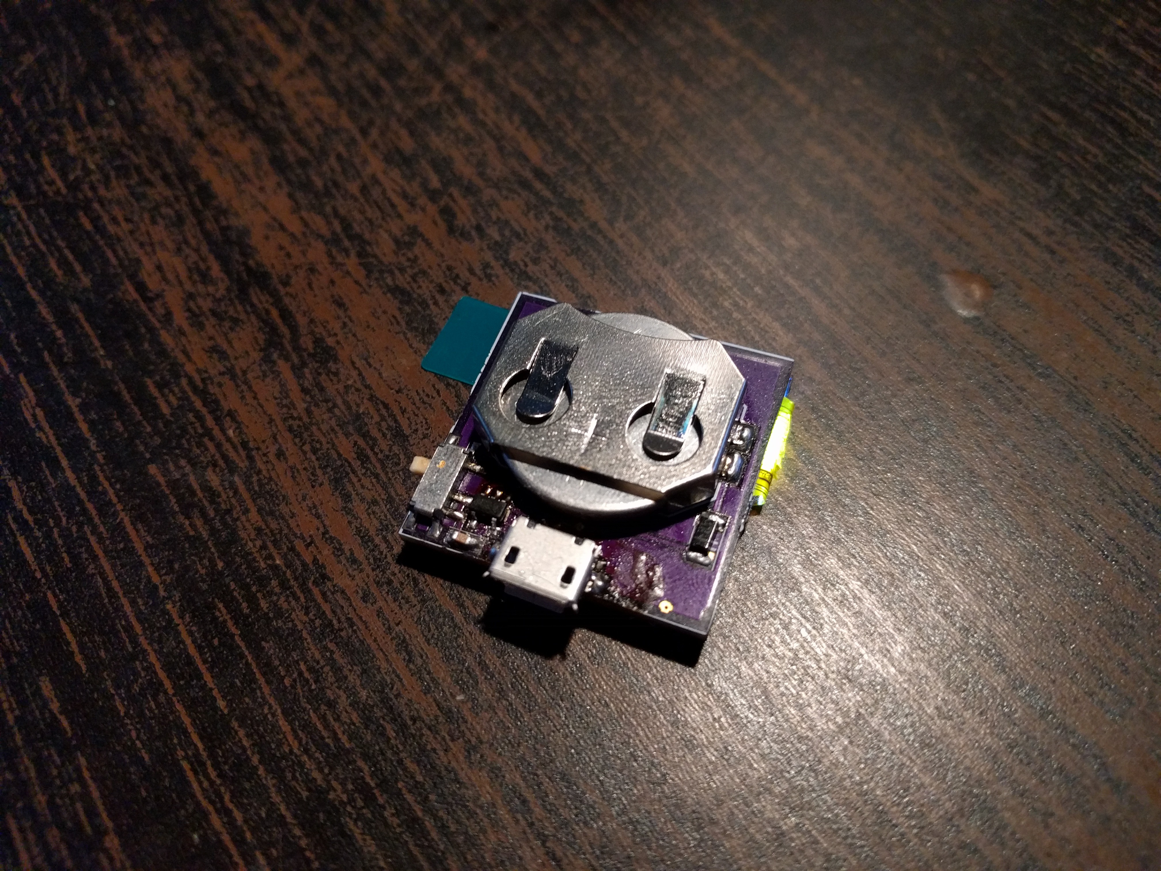
---------- more ----------![]()
On the back you can see the 2032 coin cell battery, the power switch and the voltage regulator circuit, the USB socket and the shottky diode that isolates the battery from the USB power. There is no battery charging, no audio output, no battery monitoring and even no reset button (you can reset it to get to the bootloader by shorting one of the vias to ground). I still have some free space in that corner (and it's also free on the other side), so I might add a hole for a keychain there...
As I said, the memory constraints are severe, and I haven't written a game or demo that actually runs on it, but I'm sure I can do it. In the worst case, I can drop the wasteful CircuitPython and program this thing with Arduino.
This whole thing is basically just to see how hard it would be to build (moderately), and use (hard, you have to press the buttons with your fingernails). Also, because I kinda felt bad switching the final µGame version to use old Nokia phone batteries after submitting this to the coin cell contest. So here, a version that still runs on the coin cell.
Also big thanks to the hackers on the #Hack Chat for helping me debug the power/USB problems.
-
Testing at the Fab
12/26/2017 at 01:46 • 1 commentApparently some fab houses can do firmware programming and testing of the devices right in the factory — you just have to provide detailed step-by-step instructions on how to do it. So I started work on the firmware flashing guide and on the test program. I also modified the version 8 PCB design that I have on order from Aisler to add the VCC pad to the bottom of the board — together with SWDCLK, SWDIO and GND they form the programming interface. The STLink clone I had didn't require VCC connected, but it also didn't program the chips consistently. The J-Link is consistent, but requires VCC to drive its own programming pins.
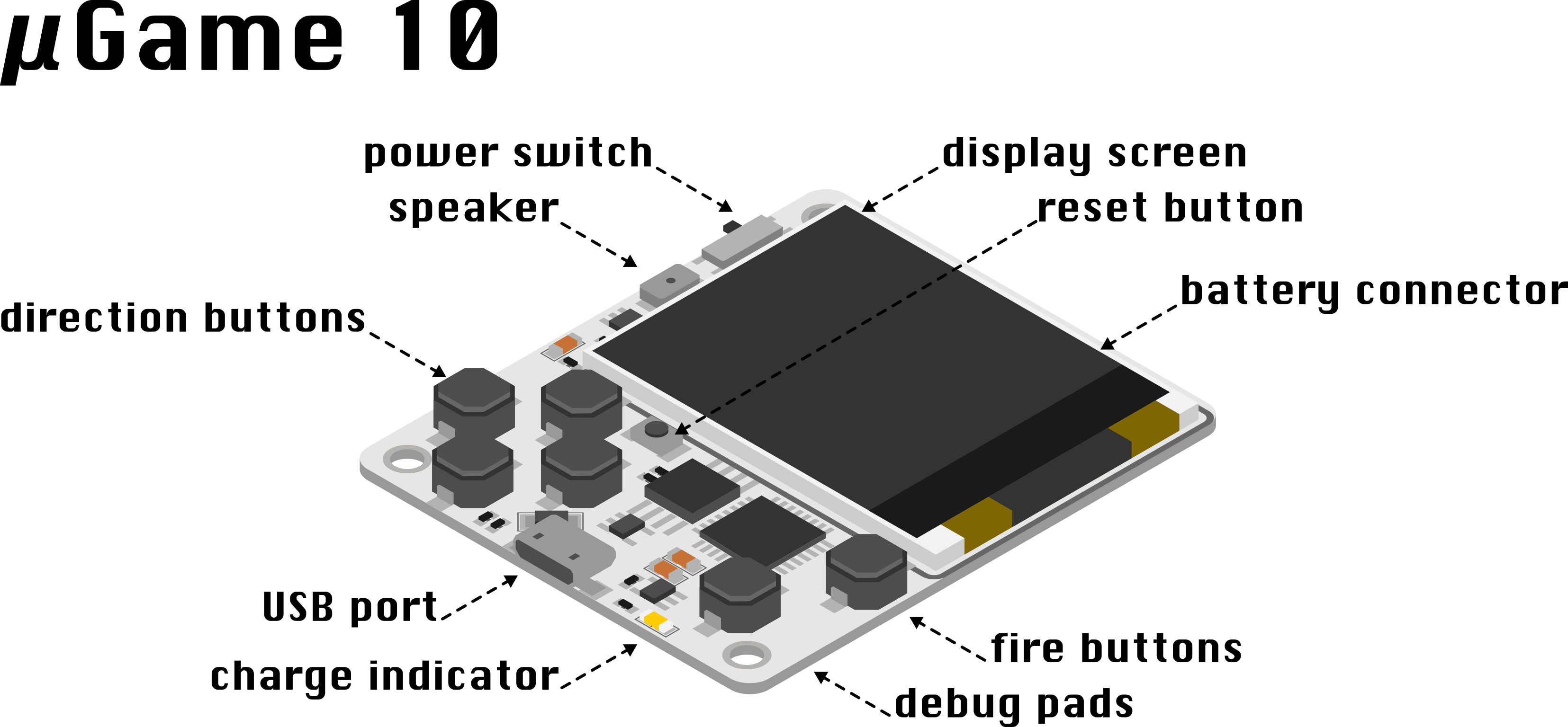
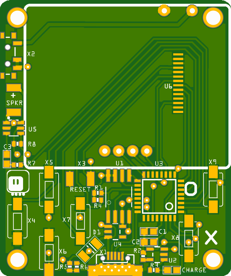
I'm also working on the guide itself, and one of the things I will need is a drawing of the board with the pads marked. So I made this:
![]()
I still need to write the actual test program, and see if I can somehow put the CircuitPython and the bootloader into a single binary to be flashed — that would simplify and speed up the process. Unfortunately the test program will still need to be copied over USB — because I also want this and the flash chip tested.
-
Version 6
12/13/2017 at 22:13 • 7 commentsThe PCBs for version 6 arrived about a week ago, but I didn't have time to work on it, between the day job and being sick. This evening I finally tested it properly:
![]()
The good things:
- moving the audio circuit was a good move, it's now completely out of reach of fingers, and I think it also seems a bit louder when the LOS is not obscured by hands,
- using straight switch instead of angled one for reset also works well — I can have a hole in the case (if I have a case) for pressing it with a pin,
- straight buttons are easier to solder,
- adding a CS pin made the displays all work consistently,
- moving the LDO away from the buttons also made it easier to solder.
There are still some rough edges, though, that I only found out after actually testing a physical prototype.
The bad things:
- the CS pin uses a via, and touching that via with your fingers makes the display stop updating — I need to route that trace on front side entirely,
- the charging LED still shines whenever USB is connected, even if the battery is disconnected — it does go off when the battery is fully charged, though,
So I scrapped the version 7 which was basically just a cleanup of version 6 ready for ordering a larger number of them, and prepared version 8. I moved practically all parts around, including the microcontroller and the flash chip, but now:
- the reset button is next to the direction buttons, not on the edge of the pcb,
- all components, except for the audio circuit, are together in the middle of the board,
- the signals for audio and for the display are routed on one side without any vias,
- there are no parts under the fingers anymore,
- the top fire button got moved to the edge to make room for the parts, so now the layout looks more like gameboy,
- all the parts are better spaced and have shorter traces between them,
- there are more mounting holes (some are under the display, but with flat heads that could still be useful),
- I have broken out four unused pins on the back, for possible hacking,
- I moved the battery connector to the other side of the board, so it now matches the layout of Nokia phone (dumb) batteries.
I know I said that about the previous version, but this is really to be the last one I'm making (at least with this microcontroller and display) — if everything works, that is. I'm going to order this one at Aisler again, to see how they improved (and to get a stencil).
![]()
-
Design Decisions
12/08/2017 at 01:04 • 1 commentOr why did I decide to build this thing the way I did. And how I could have built it differently — or maybe I will. Warning: long and somewhat rambling.
I have been thinking about building a handheld game console running Python ever since I saw the PyBoard for the first time. You know, there are not that many good choices for writing games in Python, even though it's an excellent beginner language. Somehow either there is no interest, or it's too much work with the way all of the Python's community is organized. I did some attempts of my own to scratch my own itch and fix some of the worst problems with PyGame — especially distributing the games you wrote — but with little success. Here we have a brand new community and no previous work in this area — so building something reasonable for MicroPython seeemed possible.
---------- more ----------Unfortunately, at the time I could barely afford a single board, not to mention any kind of production of boards — that board was simply too expensive for my purposes. Things changed when MicroPython got ported to ESP8266 — finally a cheap and powerful platform — but I quickly saw the problems when I ran a couple of workshops with those boards. It's simply too difficult to get them running, with serial drivers, sending files over serial, the ridiculous webrepl thing, etc. Nevertheless I started working towards the goal of being able to write games for it: I implemented the missing hardware SPI for ESP8266, a number of display drivers, a number of improvements for the framebuf module. But the progress was painfully slow, mostly due to the hostility of the lead developer of that port. I quickly became discouraged.
The port of CircuitPython to the SAMD21 microcontroller gave me new hope. Finally you can just see the thing as an USB drive, copy files over normally, no need for some silly drivers, and you can even have some extra memory storage. But the Adafruit boards were not cheap, and all the drivers and tools had to be written again. I still started to use them in my robots, and started working on the #PewPew FeatherWing — not really yet thinking about "real" games, just about some educational tool. I got seed funding for it from the Hackaday Prize, and I decided to spend that money trying to drive the cost of the whole device down. The most expensive component, by far, was the Feather board it required — so I looked into integrating it into a single device. I have built a lot of prototypes, initially copying the Adafruit schematics for the Trinket M0, and then extending and modifying that. You can follow most of that process on PewPew's project logs. But in the process I became familiar with that microcontroller, I realized that the microcontroller itself is relatively cheap (around $3), and that there will be absolutely no problem adding the C code I need to the CircuitPython repositiories. In fact, I already added a "gamepad" module there, which I needed for proper handling of buttons.
So I revived my old dream, and when I saw a number of different handhelds here on hackaday.io, including the #LAMEBOY, #Game-o-Tron Mini and especially #Game65, I decided to give it a try. The prize has ended and I needed some break from PewPew anyways (but I'm not abandoning it).
I decided on a number of constraints:
- has to use commonly available components,
- has to be smaller than 5×5cm, for cheap PCB manufacturing,
- has to use a color display,
- possibly cheap,
- four direction buttons and at least two fire buttons (accept, back),
- USB interface,
- using the SAMD21 microcontroller,
- running a basic sprites-and-tiles engine,
- nice to have: sound, battery charging,
For display, I basically had three choices among the commonly available modules: ST7735S, SSD1331 and SSD1351. The last two are very nice OLED displays — which gives me good angles and low power consumption — but they are relatively expensive, and require some scary electonics like voltage booster, so I would need to use them as modules with all the stuff already included — around $20 a piece. The ST7735 display, on the other hand, can be found for less than $3, has reasonable angles if mounted correctly, and can be driven quite fast over the SPI. And doesn't require any extra parts, except maybe for a current-limiting resistor for the backlight. So I went with that.
The choice of display pretty much determined the shape of the console. It was too big to try to go with the horizontal orientation — that left me with the Game Boy layout, with width of the display and height of the 5cm maximum. I used the smallest buttons I had available at the time — same as the ones used for reset on Pro Mini boards — and I had to arrange them in a swastika shape to make them fit in the limited space. But I also realized that I can fit most of the SMD parts on the same side of the board, so I tried hard to do that. I almost succeeded, with just the speaker and the power and reset switches being on the back. I never actually fabricated the first version of the PCB — I let it sit there for a few days, and I was still wondering whether I'm ready for this project.
Then I got some more inspiration, cleaned up a few things and created version 2, which I ordered from OSHPark. A big part in this had the fact that I just received another coupon from OSHPark, and they promised to upgrade the shipping on my order. If not the generosity of OSHPark, I would be probably still sitting on the board designs.
The board arrived, and I assembled it. There were some problems with it, like the power shorted to the ground by a button pad, but nothing a sharp knife and some wire couldn't fix. I had a first working board, and I needed some way to test it. Since I already had some games for PewPew, I quickly adapted its library to use the display, and had Snake and Tetris running on it!
But even this initial code showed a problem that I will be probably struggling with in this project for a while. The SPI peripheral on the SAMD21 chip runs at most with a 12MHz clock. Image data requires 2 bytes per pixel, and the display has resolution of 128×128. That means that updating the whole screen takes considerable time — enough to be noticeable, especially since there is not double-buffering, so you see all the screen updates as they happen, pixel-by-pixel. My previous test were done on the ESP8266, which had a 80MHz SPI, with the possibility to switch it to 160MHz — that was already too fast for this display, though.
But I decided to give it a try anyways, and tried to write a software library that would give me the sprites and tiles I wanted, with the possibility of only updating small parts of the screen, as needed. I initially wrote it in Python, using all the tricks I could think of. And it worked reasonably well with a few 16×16 pixel sprites on the screen. Updating the whole screen took some time, but once that was drawn, you didn't have to update it — at least for the games that I had in mind. When I rewrote the important parts in C, even the whole-screen updates became reasonably fast — not instant, but also not very bad.
Here's an opportunity for potential improvement: I'm using the display in 8-bit SPI mode, because that's the easiest to program and also the modules that I had only had those pins broken out. But it is possible to use a 20-pin version of this display, and use the 8-bit parallel mode to send the data. With the same clock that would be 8× faster. And I think that the SAMD21 might even have some DMA mode for this kind of thing. Of course that would mean a considerable modification both to the software and the hardware, at a level that I'm not yet very comfortable with. I still have the 20-pin version of the module in my drawer, and I just ordered an adapter for it, so I might give it a try at some point.
After testing the first (second) version of the device, I started designing the third. The actual viewport of the screen wasn't centered, so I made the board a little wider at 42×50mm — exactly the same dimensions as the Micro:bit. I moved the power and reset buttons to that narrow strip by the display, which allowed me to fit everything on one side finally (except for the battery, of course). I used the coupon and upgraded shipping again, which means I had the board next week.
Version four followed shortly. The speaker I used turned to be too weak, so I stole the amplifier circuit from the CircuitPlayground Express schematic, and moved the fire buttons to make room for it. Also, the tiny 4×4mm speakers arrived, so I used them. I did some experimenting with the battery charging circuit, trying to make it possible to charge the battery while the device was switched off but connected to USB. That backfired on me, since the charging LED was now always on, even with the switch off and device disconnected from USB — which didn't bode well for the battery. However, I was happy enough with this version, that after just reverting the charging to Adafruit's original schematic, I ordered ten boards of the version five.
Version five PCB was ordered in China, and it took some time for it to arrive — but that is fine, because I had a two-week vacation in the mean time. I only did some little work on the firmware during that time. Finally the boards arrived, and within a few days also all the parts needed for them. So I assembled six of them (scavenging displays from the old versions) and I sent them to some people who I wanted to give me their opinion on this. The packages are still in transit.
I have a version six PCB ordered right now. It has a few improvements with fabrication in mind: better mounting holes, more distance between components, buttons all aligned at the same angle. It also has the audio circuit moved in place of the charging circuit, and vice versa, because turns out that touching the amplifier input with your fingers is not good for sound quality for some reason. The board also has doodles on it, inspired by some designs I saw in the mean time. Oh, and this version actually connects the CS pin of the display, because it turns out to be necessary for some of them (but not all, weirdly enough).
There has been some improvements in software too, mostly driven by the game I wrote for the 40th Ludum Dare challenge. I also hit another limitation of the SAMD21 chip here: limited RAM. I had to compile the game into bytecode to make it fit.
Which leads to the next possible improvement: SAMD51. That's an ARM Cortex-m4 microcontroller, freshly released by Atmel, with whooping 256MB of RAM, and only $2 more expensive than the SAMD21. And CircuitPython is getting ported on that even as we speak. No 32-pin TQFP package, though, so I might need to redesign the board completely if I decide to switch. Together with the parallel protocol for the display, that would make the perfect console for me — I might even be able to do scrolling. But this is potentially a lot of work and unknown unknowns, so who knows when it might happen.
This is also one of the reasons why I'm hesitating from fabricating and selling this. I know that a lot of people would love to get their hands on it, especially if I managed to keep it cheap, but I don't want to be stuck with a stock of obsolete devices when a new version comes.
-
Sound Issues Resolved
12/05/2017 at 11:19 • 3 commentsAs usual, the problem was in software. Actually, not even that, it was in the data. Turns out the .wav files I used were at fault — they didn't start at a zero value (hence the clicks at the beginning) and they were truncated compared to what was specified in their headers (hence the buzzing at the end). Running the files through sox fixed both problems and gave me nice retro sound:
Yes, there is a bug with the missile not getting deleted halfway through the game.
-
Audio Woes
12/03/2017 at 20:17 • 0 commentsIf you watched my previous video, you surely noticed that the sound is very bad. That's not the recording, the sound *is* very bad. I get a lot of clicking, buzzing and droning, even if nothing is playing. I think the clicking may be coming from the wav files not beginning/ending on a 0, and at least part of the buzzing is from my fingers touching the audio in track on the back of the PCB, but there is definitely something more going on.
Needless to say, I would love to get that fixed, so that is the next task. It will possibly involve redesigning the whole audio circuit. Helpful advice welcome.
-
Vacuum Invaders
12/03/2017 at 18:21 • 3 commentsMy Ludum Dare 40 challenge entry is finished: https://ldjam.com/events/ludum-dare/40/vacuum-tube
Here's the video: