• Autocode-Commmunications

    David Gitz11/16/2017 at 12:53 0 comments

    I've found that when connecting different devices together it can be a bit of a burden to manage the different comm protocol/drivers between them.  This is more a problem when connecting OEM products, such as IMU's, gps's, etc.  But as these aren't as standardized this more focuses on devices that I have control over.  

    For the Scout I have the following comm links:

    • WiFi comm between the DriverStation and the Scout (Multicast and Unicast UDP)
    • WiFi comm between the DiagnosticsGUI and the Scout (Multicast UDP)
    • SPI comm between Raspberry Pi's and Arduino Boards
    • I2C comm between Raspberry Pi's and connected Hats
    • Serial comm between Raspberry Pi's and Arduino Boards as well

    Which is quite a lot, and each protocol has different requirements.  I really wanted to make this as generic as possible, i.e. have task specific code for reading/writing to the comm port and common encoding/decoding libraries that can be auto-generated.  This is really helpful when making changes to the comm protocol.

    So here's what I've done:

    1. Create a formatted xml file with each comm message specification.  This is something like:

    <message name="Command" id="0xAB02">
            <description>
                <!--[CDATA[
                    This message is used for command messages
                ]]-->
            </description>
            <protocols>
                <protocol name="UDP">
                    <origin>GUI</origin>
                    <retry>true</retry>
                    <fields>
                        <field type="uint8_t" name="Command"></field>
                        <field type="uint8_t" name="Option1"></field>
                        <field type="uint8_t" name="Option2"></field>
                        <field type="uint8_t" name="Option3"></field>
                        <field type="std::string" name="CommandText"></field>
                        <field type="std::string" name="Description"></field>
                    </fields>
                </protocol>
                <protocol name="Serial">
                    <retry>true</retry>
                    <origin>Master</origin>
                    <origin>Slave</origin>
                    <fields>
                        <field type="unsigned char" name="Command"></field>
                        <field type="unsigned char" name="Option1"></field>
                        <field type="unsigned char" name="Option2"></field>
                        <field type="unsigned char" name="Option3"></field>
                    </fields>
                </protocol>
            </protocols>
        </message>

     Note that each message can be encoded with different protocols, such as UDP and SPI.

    2. Created a python script that reads in this xml file and outputs the encoder/decoder code.  Currently I have to support 3 systems: Qt, Arduino and ROS.  Each of these systems has slightly different implementations, for example the Arduino autocode has different data types than the Qt autocode.  This script also copies the autocode to the appropriate locations on my development computer.

    3. Add/update the write/read methods in each task that are affected, as the function definitions in the autocode files will change based on the message definition.

    So far all the autocode files are in C++, I prefer to not use python in my projects as it tends to not run as fast.  I hoped this helps with other people's projects.  Here are some links:

    Autocode Message Generation

    Example Raspberry Pi auto-code using SPI and I2C

    Example Raspberry Pi auto-code using UDP

    Example Arduino auto-code using Serial and SPI

    Example Qt auto-code using UDP

  • Camera Pan/Tilt for the Raspberry Pi Camera

    David Gitz11/04/2017 at 14:18 0 comments

    For my project I wanted to have a pan/tilt mount for the Raspberry Pi Camera that I can control remotely and view the video stream in a GUI.  I found adafruit's pan/tilt mount but I wasn't a big fan of it, I didn't like the mounting options a lot.  And with my new 3d printer I wanted to try it out by designing something useful.  So I designed my own pan/tilt mount.  I put the design files on grabcad here.  I went through several iterations of this and I like how it turned out, but I think if someone was to use this they would want to reinforce the pan bracket a little more.  Also, the mounting location for the tilt bracket should be moved up a bit to increase the range of motion.

    So this is great and all.  But how do you get the video stream?  After a lot and lot of googling I figured out how to start a TCP stream on the raspberry pi and send it to a GUI in QT.

    On the pi run:

    raspivid -t 999999 -h 480 -w 640 -fps 25 -hf -b 2000000 -o - | gst-launch-1.0 -v fdsrc ! h264parse !  rtph264pay config-interval=1 pt=96 ! gdppay ! tcpserversink host=IPADDRESS port=PORT

     The GUI code is a bit more involved, but for an example you can view what I'm doing here.  This includes how to convert it into a QT pixmap suitable for overlaying image data as well.  That's all for now, I hope this was useful.  I think next time I'll talk about how I'm doing the auto-generation of code for different comm protocols/messages.

  • System Architecture

    David Gitz10/29/2017 at 13:14 0 comments

    I wanted to spend a little time talking about the system architecture for this and other projects I'm working on.  When developing this I tried to make it as scalable as possible.

    The first figure here is the "back-end", this is the device tree that is common to all my projects.

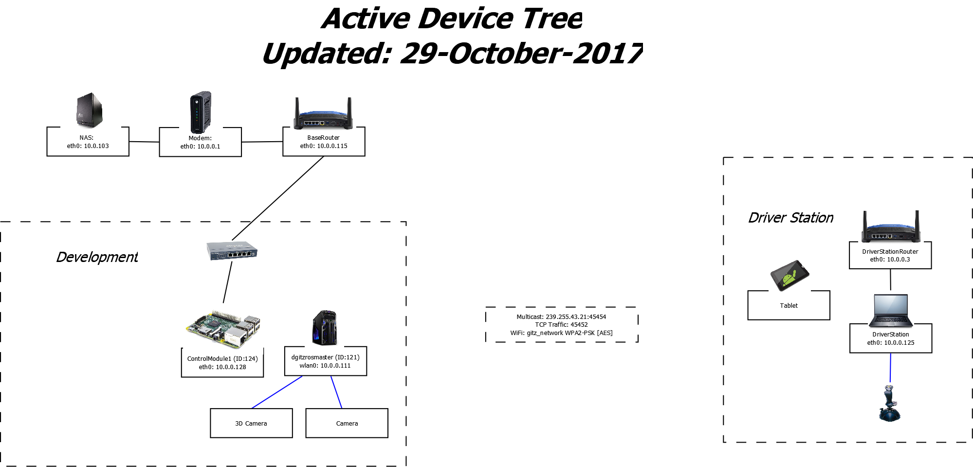
    As can be seen here, devices are connected to each other over either a wired LAN or a WLAN network, but these 2 network segments exist on the same subnet.  Any device that has a network interface can see any other device.

    There are similar diagrams for each project that are project specific, which I am still creating. The document here details each device by function, what it does, the FAST PN's that are supported and how it should be configured.

    The system is designed to be auto-configured as much as possible.  To that end, all device configuration information is stored in project specific xml files.  The main file, the DeviceFile.xml (example here) is used throughout the ICARUS software configure itself.

    I hope this has been a little helpful.  There are definitely more pieces to this, such as how the different ROS nodes pass device information around, what the different comm protocols are, etc.  I think next time I will talk about the camera pan/tilt mount I made for this project.

  • Part Database

    David Gitz10/15/2017 at 12:33 0 comments

    For this project (and others as well) I really wanted a nice system for tracking parts/items.  I had been using a spreadsheet for a while but I wanted more out of it, I wanted to be able to create order reports, bill of materials, how much a project would cost, etc.  The spreadsheet system I was using was a bit cumbersome so I decided to make something better.

    First I should explain how I categorize parts.  Every item in my database has 2 special classifications, a part type and a part category.  The part types are fairly obvious, these are "Product", "Raw Material", "Documentation","Software", etc.  The part categories are a bit more involved.  Currently I have 111 part categories, these include such things as "Connectors","Spacers","Wheels","IC's", etc.  Each part category has an assigned number range.  For example, the "Connectors" type has an assigned Part Number range from 784000 thru 787999.  This Part Number range is used to automatically generate a new PN based on the part type.  This is useful as it helps to track things.

    The Part Number range I currently have ranges from 0 thru 1 million, which is a lot, especially since I only have about 500 items in the database currently.  But this is a nice scalable system that I can use for a long time, if not forever.  I should say that with this Part Number system it is easy to add in more info to it.  For example, if you have 2 different versions of the same part, you can create a part with the PN 533001A and 533001B and the system will still work fine.  One of the things I want to add in the future is the ability to create BOM's based on the part number.  For example, if you have the PN 653002-0X1 and it's designed as a BOM item, you should be able to generate the BOM that this item would represent, given the -* identifier.  

    The database I'm using now is based on MS Access with a lot of VBA code behind it.  This was really helpful to me when I started making it, as it's a pretty straight forward system to make a database from scratch.  In hindsight I would have rather used a web-based database so I can use it on other devices.  Maybe someday.

    So I think it's time for some pictures.  When you open the database you get the main switchboard:

    It is split out into "Search","Projects",Part Update" and "Inventory", which are all self-explanatory.  For part search, it matches on any text in the PN field, item name or description and pulls up a report with all the items that match.  You can also search on Item Category, Supplier and Type.

    When you click on one of the search results it will pull up the Item Viewer.  This has all the detailed info on the Item.  

    For Items with the type "Locally Fabricated" you can click on the Fabrication Steps link to see how to fabricate this item.

    The database also supports projects.  You can add any item (in any quantity) to an existing project with an associated system and subsystem fields.

    You can see a project's complete BOM and edit directly from the BOM editor.

    Besides a BOM report and an Order report you can also generate a Fabrication report, which is useful to tell you all the things you need to fabricate for this project and all the fab steps for each item as well.

    And finally you can see all the current tasks for a project.  These tasks are things you manually enter, they don't link to any items in the database (yet).

    This was definitely a brief overview of the database.  There are a lot more cool things that it can do.  For example, every time you create an item it will create a folder in the Library Path that has the following sub-folders: "ANALYSIS,DATA,DOCUMENTATION,ELECTRICAL,MECHANICAL,MEDIA,SIMULATION,SOFTWARE".  This is very useful when dealing with other design programs, now you have a central database for...

    Read more »

  • Background 1

    David Gitz10/12/2017 at 03:10 0 comments

    I thought for the first few logs I would just give an overview of the system I have in mind.  I have already done quite a bit of work in the design and build process for this project, so these logs are going to be catching up to reality for a while.  Forward then.

    I started working on the Scout about 6 months ago.  I had just finished up working on my Thesis Rover (repo) and had found that the drive system for that rover was not doing so well.  I haven't built a robot from scratch in a while so I thought now would be a good time.  However, I don't have a lot of machining tools, I have a drill press and recently purchased a 3D printer but no lathe or CNC tools.  Making robots from scratch can be a bit challenging, especially with the drive systems.  It can be a daunting task to build a robot that isn't too expensive and that has a decent amount of power.

    One thing that had always bothered me with robot building was that there isn't a lot of COTS drive system products that one can find locally, and even for the large electronic supply stores (Like Fry's) which does have some of this stuff, it can be very expensive and you are more or less locking yourself into their build system.  What's worse is that for most people I would think the actual frame building process wouldn't be very challenging, Aluminum isn't too hard to work on with hand tools.  It's the drive components that are a killer.  The question, "How do you mount a wheel to a motor?" quickly evolves to: "How do you mount a wheel to a motor with a different gear ratio on a suspension that can pivot?"  

    I realized that the answer to this question was staring at me in the face.  RC hobby stores are pretty common, and they make a living on selling drive components (motors, servo's, linkages, suspensions, gearing, etc) for applications that are approximately the right scale, weight and price for the average robot hobbyist.  But the people who usually go into these stores and buy individual parts already have a large amount of experience in the RC field.  Indeed these parts (online or in a brick & mortar store) are going to have very few (if any) dimensions and be marketed solely as replacement/upgrade parts for specific vehicles.  This is not what we want, we are building something from scratch!

    So I decided I was going to learn.  I would design a frame based on common material (Aluminum), brackets from hardware stores and 3d printed options, and drive components from RC parts.  Additionally I would design the Scout around a toy Caterpillar 992C Wheel Loader that I had, and the Tracks from an old H2 Hummer (RadioShack) just to make it a little more aggressive.

    Next time I will talk about my current Inventory System.