allai5
-
Improvements
10/16/2017 at 03:26 • 0 commentsWe’re thinking about what to do next for our ROV. We would like to be able to implement filtration technology in addition to the detection technology that we already have, but we were also considering moving electronics to bottomside. This would greatly enhance our ROV as we could use more powerful thrusters and take in more sensor data. We would also like to try to test our robot in more real life scenarios. If we could actually monitor a body of water for an extended period of time, we would be able to see how to improve our robot so that it can be used commercially.
![]()
-
Buoyancy
10/16/2017 at 03:23 • 0 commentsWe needed a way to easily adjust the buoyancy of the ROV depending on the density of the body of water that the robot is in. We tried attaching various “ballasts” to the ROV using environmentally friendly duct tape. We started by taping rocks to the robot to weight down different parts of the robot. This proved to be impractical as these rocks couldn’t be easily adjusted in a real life scenario. We then tried to tape styrofoam to the frame, but this was impractical for the same reasons as the rocks. We finally added Arizona Iced Tea bottles which are perfect as they can be filled with water to easily adjust buoyancy at any time.
![]()
-
XBOX Controller
10/16/2017 at 02:32 • 0 commentsWe needed an intuitive control scheme and a portable controller. After going through many styles of joysticks, from small 2-axis potentiometer joysticks to large USB joysticks, we' decided that the the XBOX 360 controller would be the most intuitive ROV controller. Moreover, an XBOX 360 controller can be commonly found in households, further lowering the cost for the ROV.
Although, this gaming controller has many joysticks and buttons, we only needed two joysticks to control all the motion on the robot. One joystick controlled forwards, backwards, and turning motion, while the other controlled lateral, up, and down motion. The joystick feedback was sent to a wireless receiver which was connected to a USB Arduino shield. We struggled with the receiver as the controller kept dropping its connection. We solved with this by doing several power cycles. Finally, we had developed a control scheme that was user-friendly and effective.
![]()
![]()
-
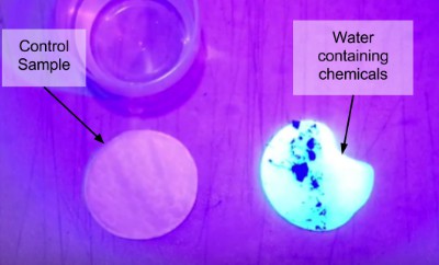
Ultraviolet Light: Detecting Optical Brightening Agents (OBAs)
10/16/2017 at 02:16 • 0 commentsWe needed a way to detect pollutants in the water. According to recent studies, shining ultraviolet light on water samples, pollutants will glow a bright color. We tested this with water samples collected by the ROV. We found that the UV light was able to highlight the sample that contained chemicals commonly found in laundry detergents. Thus, we successfully developed a low-cost method for find pollutants in water.
![]()
![]()
-
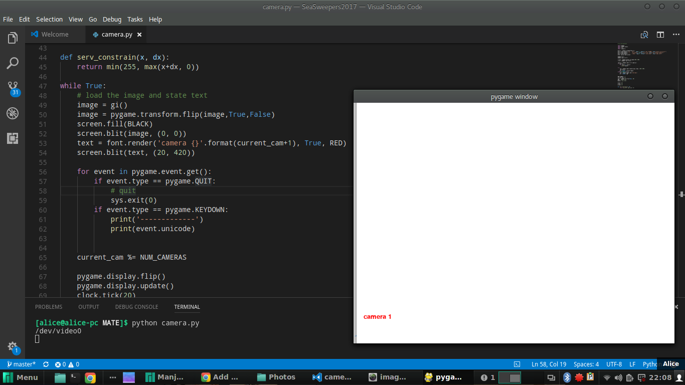
Camera System
10/16/2017 at 02:10 • 0 commentsSince we are using a low-cost backup car camera, the camera feed is inverted, but for intuitive control of the ROV this needs to be reverted back to a normal, “forwards” view. To do this, after threading the camera through the tether management cross, we plug the RCA plug of the camera into the video plug of a USB capture card. Using a Python script and the pygame library, we are now able to concurrently revert the camera feed and display it on the operator’s laptop.
![]()
![]()
-
L298N Motor Controllers
10/16/2017 at 02:04 • 0 commentsWe finished the final version of the motor controller circuit! To make the ROV more low-cost, we've replaced the Sabertooth motor controllers with L298N H-Bridge drivers.
The primary purpose of the circuit on our ROV is to take input from a program and use this input to control the motors. First, the Arduino microcontroller reads pulse width modulation (PWM) inputs from two joysticks that act as potentiometers. In addition, the orientation of the joysticks tells the motors whether to turn clockwise or counter-clockwise. The Arduino then sends data signals to L298N motor controllers. These serve two purposes. For one, they can be used as h-bridges which can output a negative and positive voltage so that the motors can turn both ways. Secondly, they take in a PWM signal ranging from 0 to 255 so that it can output any voltage from 0 to 12 volts. Initially problems arose as we tried to ensure that the motor controllers could handle the current drawn by the motors. We performed calculations using Kirchhoff's Law to calculate the current drawn from and the voltage needed for the motors. We then had to measure these values in practice using a multi-meter. After this we tested our circuit and we found that it gave the robot the ability to turn and move forwards, backwards, and laterally at varied speeds.
-
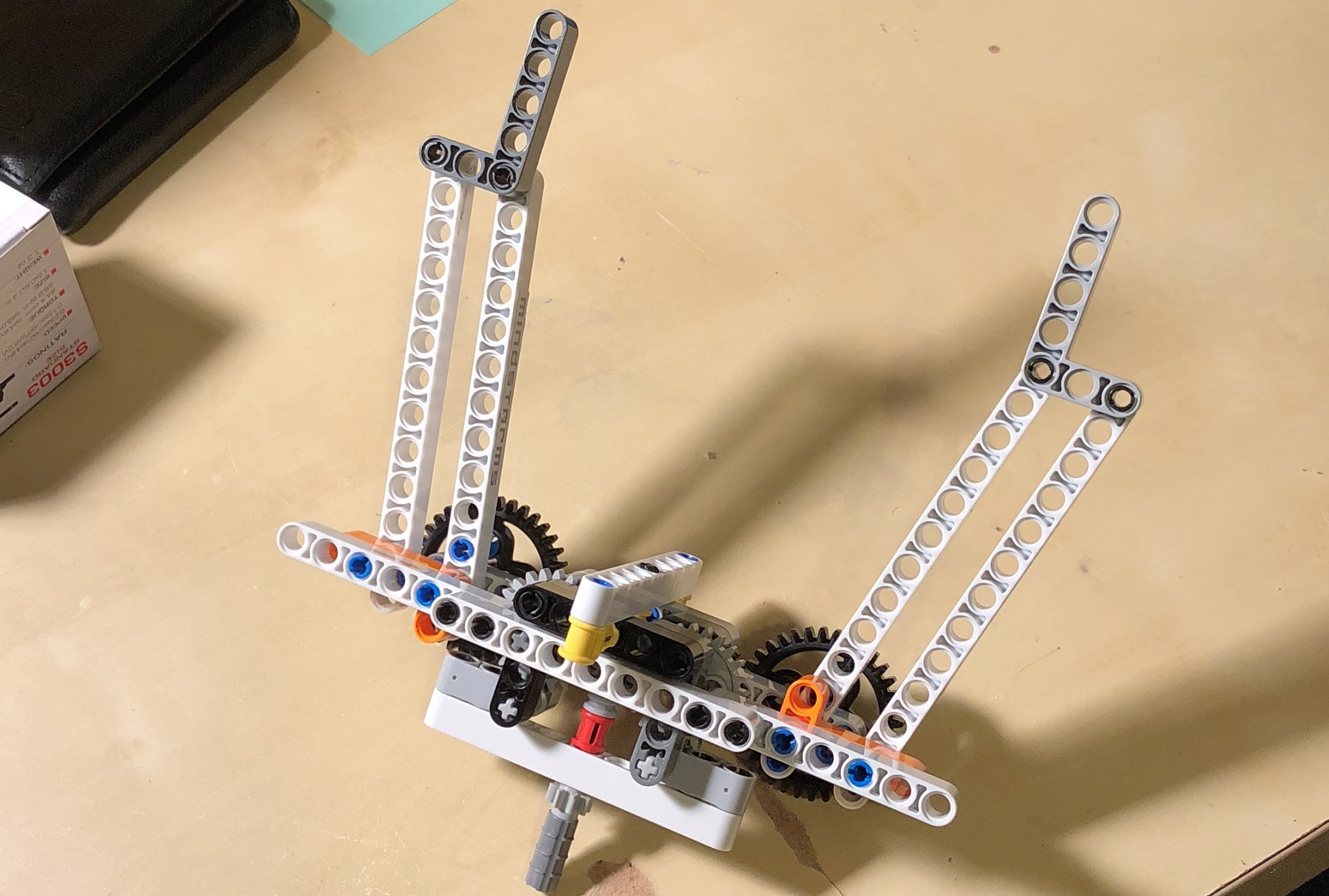
Claw
10/16/2017 at 02:01 • 0 commentsWe have a few different claw designs for Volturnus. We initially tried a simple Lego claw, but we found that it wasn’t secure enough for our 500 gph bilge pump motor. We then thought about implementing a passive claw design--this would be cost-effective and free a motor for something else--but it would be difficult to adapt to the variety of different obstacles found underwater. Finally, we were thinking about building a more professional claw with 3D printing and metal gears, but we have not yet been able to implement it. We will need to run more tests in the future to see which claw design will work the best. Perhaps this is something that we should approach from an angle of modularity?
![]()
-
Topside Electronics Box
10/16/2017 at 01:58 • 0 commentsThe topside electronics box is finished! The electronics box allows us to provide power and control through two joysticks and Sabertooth motor controllers. A cable with banana plugs connects to a 12V DC power supply, then runs through an in-line fuse, kill switch and watt meter for power and monitoring. The 12V then goes to the SeaMATE motor control simulation board, receiving inputs from the joysticks and Sabertooth motor controllers.
![]()
-
Tether Management Cross
10/16/2017 at 01:56 • 0 commentsOur tether has been attached--we opted for a lightweight tether with eight wires, two for each motor (3 drive motors and an additional motor that can be used for the claw). This allows our ROV to remain maneuverable in the water without getting weighed down by a heavy tether. Because electronics are being handled topside, there is no need for anything more than these wires.
-
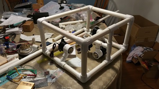
Assembling the ROV frame
10/16/2017 at 01:38 • 0 commentsThe ROV frame has been constructed! The frame is a simple rectangular box made from PVC--this offers the most versatile and cost-effective design. Currently, our frame has dedicated PVC connectors for mounting motors. While this is certainly very easily modifiable, it might be easier to position motors with snap-on components.
![]()
Volturnus ROV
A low-cost, DIY ROV (Remotely Operated Vehicle) to detect marine pollution in local communities.