Well I managed to snag an NX-4 control box off ebay for 100 bucks last week! It was a total pig in a poke (kind of like the LED tiles were) but it seems to work, at least enough to drive the displays! I have it showing test patterns and stuff now using it.
The wiring is now figured out for the cables, and it works like this:
(8 pin "out" connector -> 9 pin "in" connector)
1 - > 1 (+24V)
2 -> 6 (GND)
3 -> 7 (out data to display positive)
4 -> 3 (out clock to display negative)
5 -> 5 (in data from display positive)
6 -> 2 (out data to display negative)
7 -> 8 (out clock to display positive)
8 -> 4 (in data from display negative)
It appears the cable from the NX control box to the tile, and the cable between tiles is the same. I guess this would make sense.
Inside the NX control box proper is a huge 24V, 15A(!) power supply. It has an IEC receptacle on it, but unfortunately it is only for 240V operation. It will not run on 120V. The supply is extremely high quality and has a very small for this power level planar transformer inside and a PIC micro. It also has I^2C for some reason. I cannot use the existing supply so I am just hooking my bench supply up for now and running a single tile.
A quick scoping reveals the clock going to the display is 50MHz which is a bit higher than I was expecting but not too far out of the ordinary I guess. I initially didn't twist my pairs because I was lazy, and it resulted in it not working very well at all.
Holding the wires together with my finger seemed to make it work a lot better and I started to get actual data on the display! Interesting how the word "up" was showing up in green at the bottom there.

Finally, after doing it right and twisting the pairs, it seemed to be working properly.
There's a two position dip switch on the board with the text "sw this way for normal operation" with an arrow. If both of the switches are in the down position, it will display a moving white grid pattern that marches down and to the right one row/column every 300ms or so. I assume this is so you can tell if you have arranged the tiles properly in the array and have not turned one or more of them.
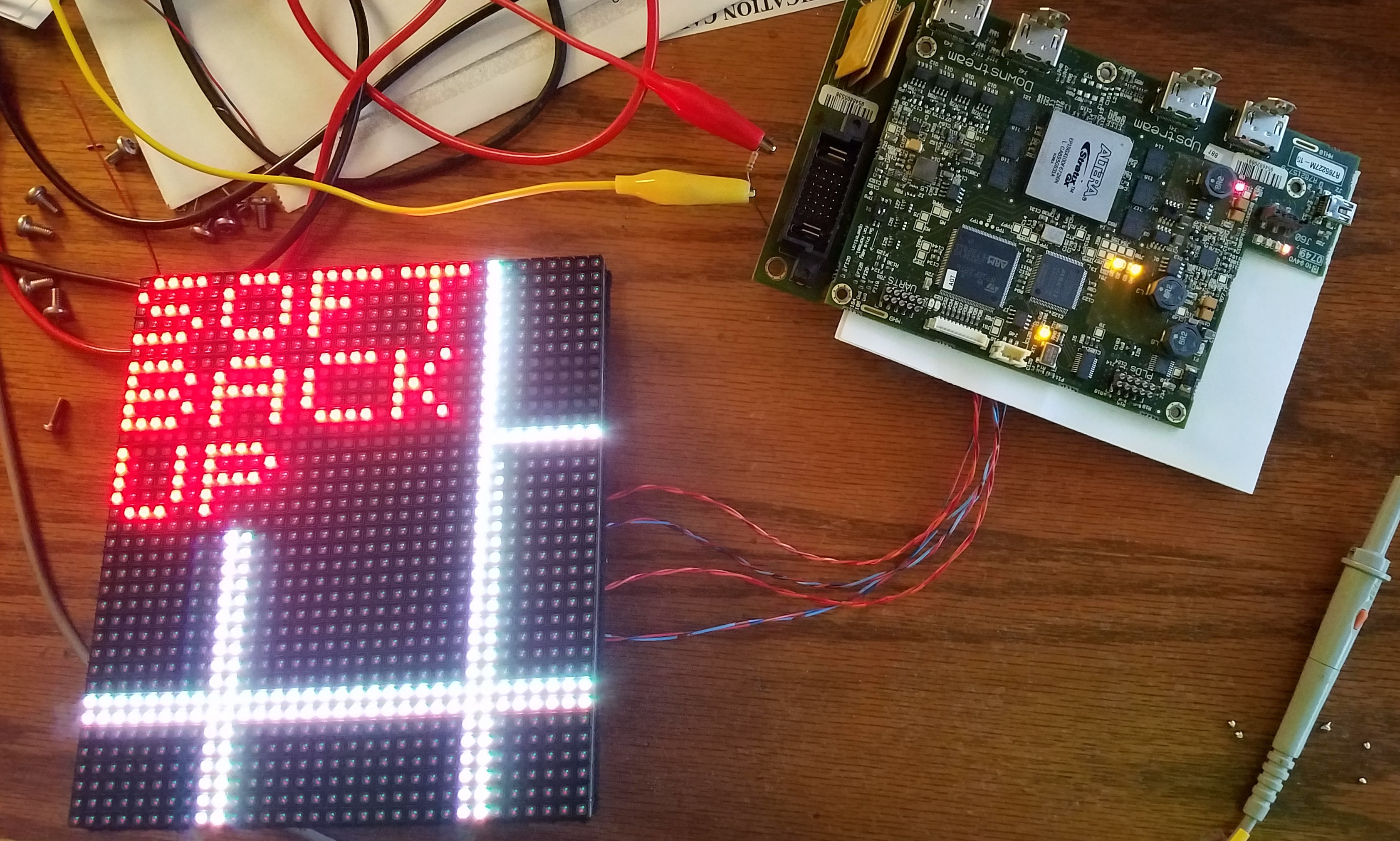
If one switch is up and the other is down, you get the "soft back up" message with the marching row/column behind it. I am not sure what this means but it is probably documented in the manual.
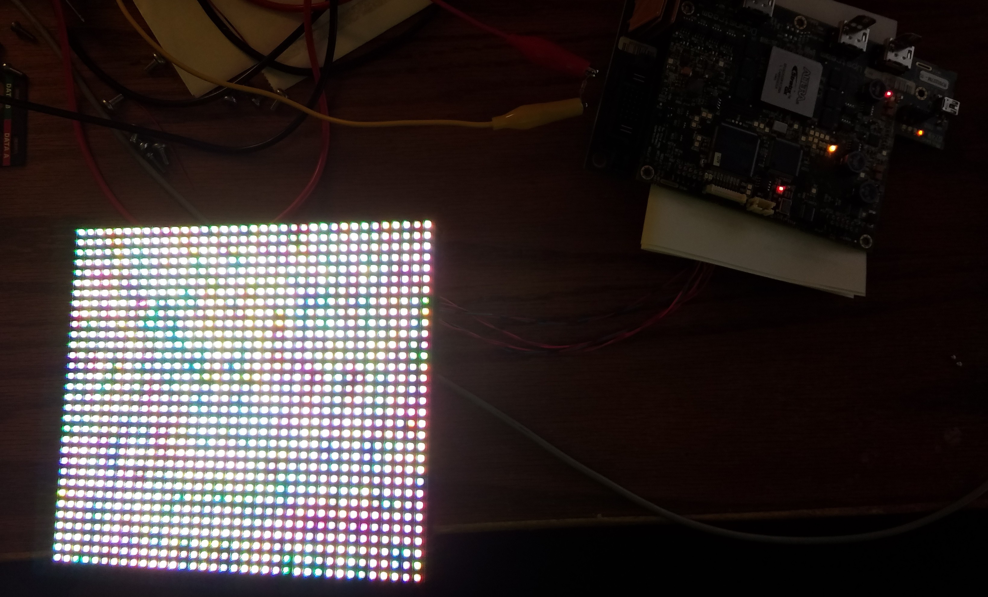
Clicking both up in the "normal" position, results in all LEDs glowing a dim grey, I suspect for LED testing or similar. On this panel all LEDs appear to light and with absolutely uniform brightness.
There's a ton of LEDs on the control PCB and they all flash various patterns. I am not sure what they mean but there's four LEDs near the connector to the indicator LEDs for the box which indicate status. One flashes yellow about once a second (sometimes it will flash twice in a pattern) and the other flashes orange 3-4x a second.
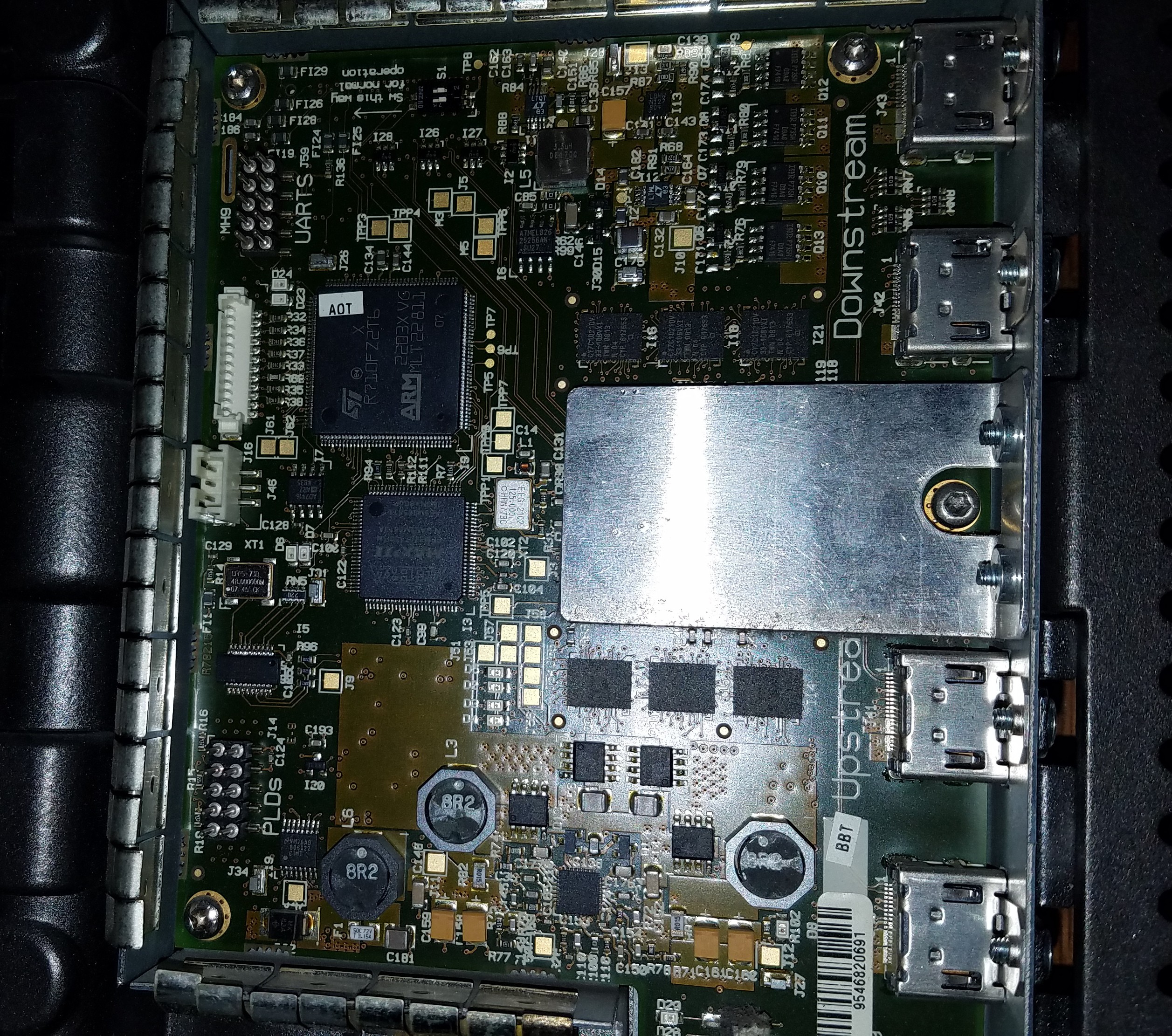
Hardware on the control board is pretty brute force. There's an ARM CPU, Stratix GX FPGA (with 8 serdes, two per HDMI connector to link the control boxes together as shown in the docs), 6 128Kbyte 15ns SRAMs, a maxii CPLD, and a bunch of power supplies.
On the bottom is a 4mbyte parallel flash ROM and a MAX232 RS232 transceiver. There is also a mini USB connected to the ARM, but I have not plugged anything into it yet. There are 3 big honking 9A 30V polyswitches to limit current to each string of three LED panels as well.
That's about it for now, I just got this box today and had to do a quick play around to see if I could get it to light up one of the LED panels, and it did! I hope it isn't too tough to hook this up to an FPGA and do some heavy duty reverse engineering of their protocol now.
Finally, a crappy pic of the board inside the box.
Discussions
Become a Hackaday.io Member
Create an account to leave a comment. Already have an account? Log In.
nice work! I also have one of the NX control boxes, and just wired mine up - works the same way. I have a Saleae Logic Pro 8 - would it help anyone if I captured the communication between the controller and the panel and posted it?
Are you sure? yes | no
That would be perfect. How do you communicate with the controller? What displays can you trigger?
Are you sure? yes | no
I tried capturing the signal to the panel today, but it seems that the logic pro 8 can't analyze differential signals due to not being able to set a custom logic voltage threshold... Let me know if anyone knows how to properly capture the signals!
I don't have any way of communicating with the controller though, and am just running a single panel right now (haven't tried daisy chaining yet)
Are you sure? yes | no
[Edit] Bleh. Forget what I said.
@beauburrows, I also have one of these boxes, so if you can't get your setup to capture properly, I might be able to do it with my HP 16500.
Are you sure? yes | no
How weird that @SpaceCoaster and I both had a mysterious urge to check in on this project in the last few hours, after this update has been posted for two weeks...
I'm very curious to find out what intercepting the communication between controller and panel yields - that will put us so much closer to a no-modification-required homebrew controller!
Are you sure? yes | no
Excellent!
Are you sure? yes | no
Awesome work! It'll be interesting what you can dump from the communication between the two.
Are you sure? yes | no