 modder_mike
I tried to describe this in words, but I think something was lost in translation. Much easier with a photo.
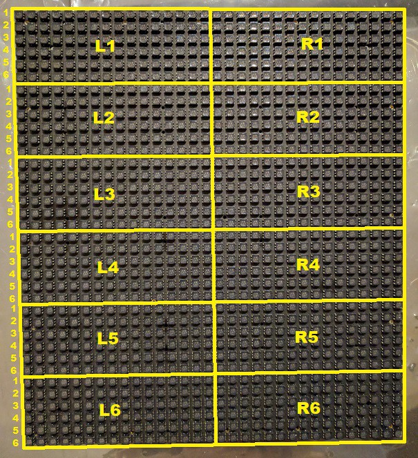
The panel is divided into twelve segments of 16x6. Each segment is driven by three Texas Instruments TLC5941 16-channel LED drivers. Each driver controls one color of the tri-color LEDs. The three drivers have their serial data cascaded, with the first controller in the cascade being Red, then Green, then Blue.
The 96 LEDs in the segment are controlled by only 16 driver channels by multiplexing the rows' LED anode voltage (TLC5941 switches the cathode side). Each of the 36 rows has a transistor between the panel's +4.5V input and the LED anodes. All like-numbered rows' transistors are connected to a common control pin on the CPLD. The CPLD cycles through them in sequence as instructed by the FPGA, synchronized with the incoming display data.
Take care when rewriting HDL for the FPGA. Because the LEDs are expecting to be run at only 1/6 duty cycle, they may theoretically be damaged if they are not cycled as quickly by user HDL. (For experimenting, consider using the calibration LEDs on the rear of the panel, which are not multiplexed.)
Discussions
Become a Hackaday.io Member
Create an account to leave a comment. Already have an account? Log In.