I've nearly completed building my own home, and have used the loxone mini-server to supply the home automation. When specifying the server, we quickly realised we would have to find another solution for all the digital io.
We have 43 light switches - but each light switch has 4 contacts - making 172 inputs just for the light switches. Add to that 20 door & window sensors, plus blind controls, PIR sensors, under floor heating actuators and pumps. You get the idea.
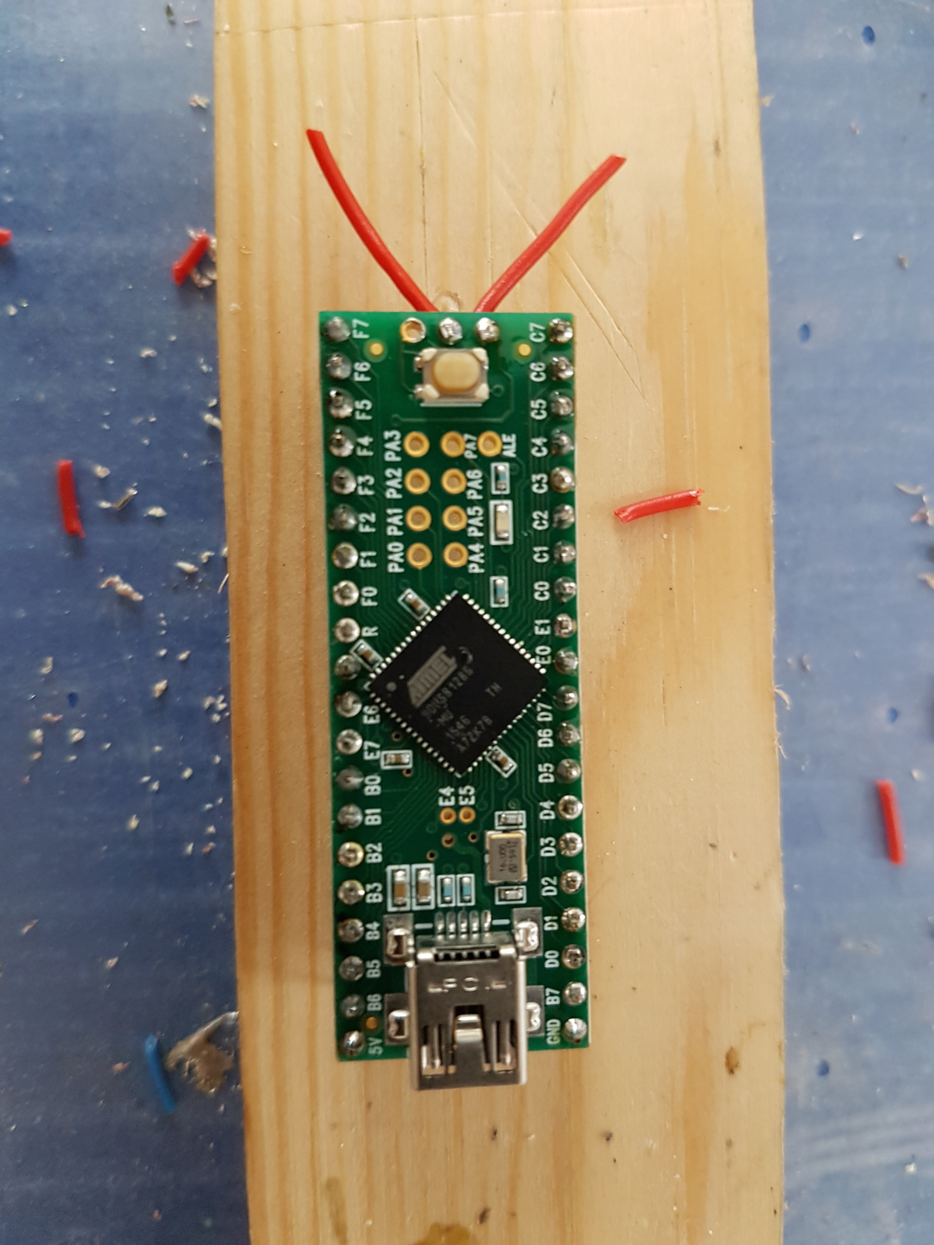
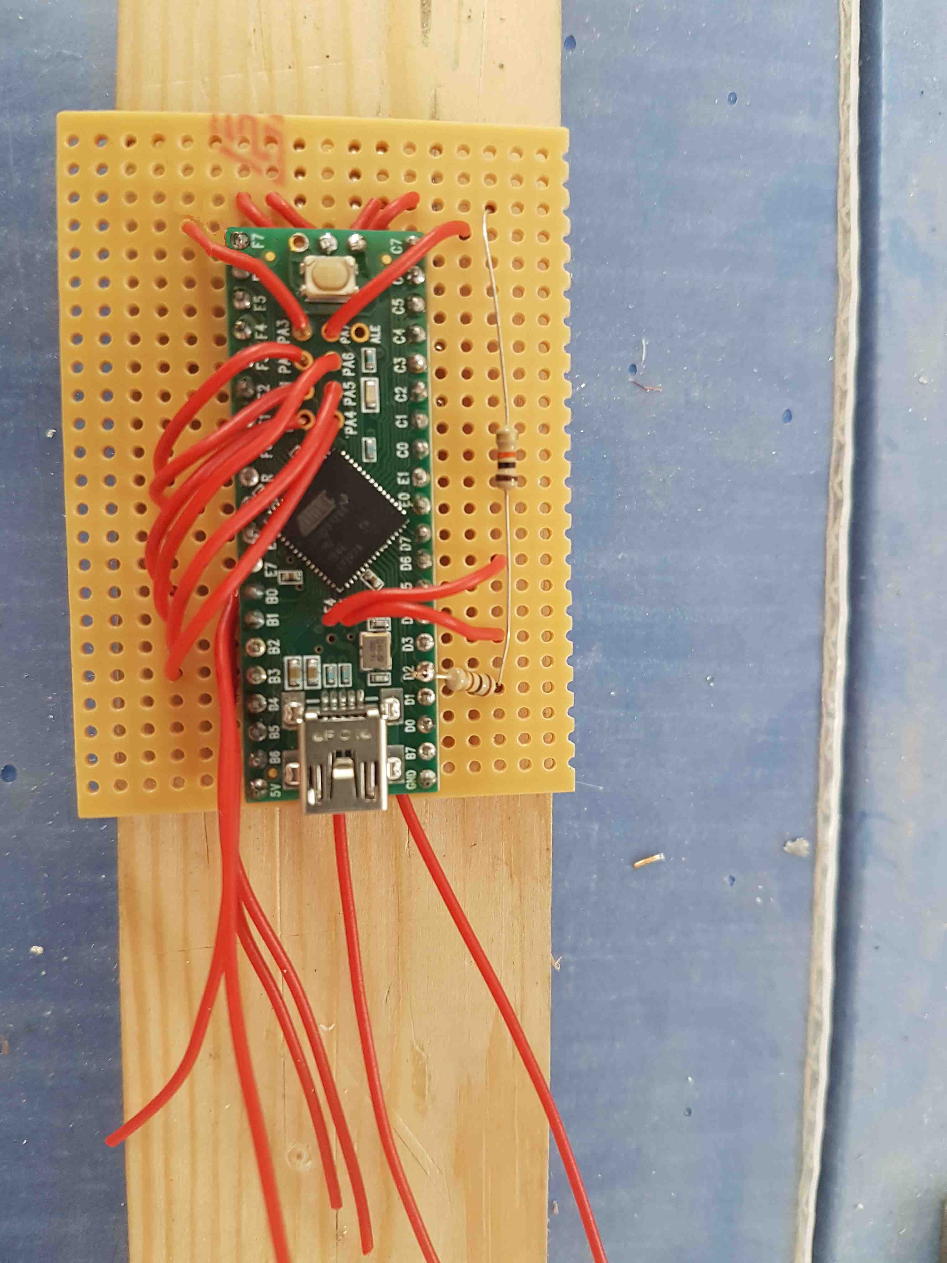
I chose the teensy 2.0++ as it had a large number of digital IO on the board. We did consider using I2C io extension boards, but physical size is a factor and it was easier for us to make it compact using the teensy.
I'm not a hardware expert at all! But the system we have made is bullet proof reliable. The software and interface to the loxone does not use any polling at all- so all the double/triple clicks work flawlessly with the loxone system.
The boards have a web interface which is really important for setting up and diagnostics as you have feedback showing which inputs or outputs are active.
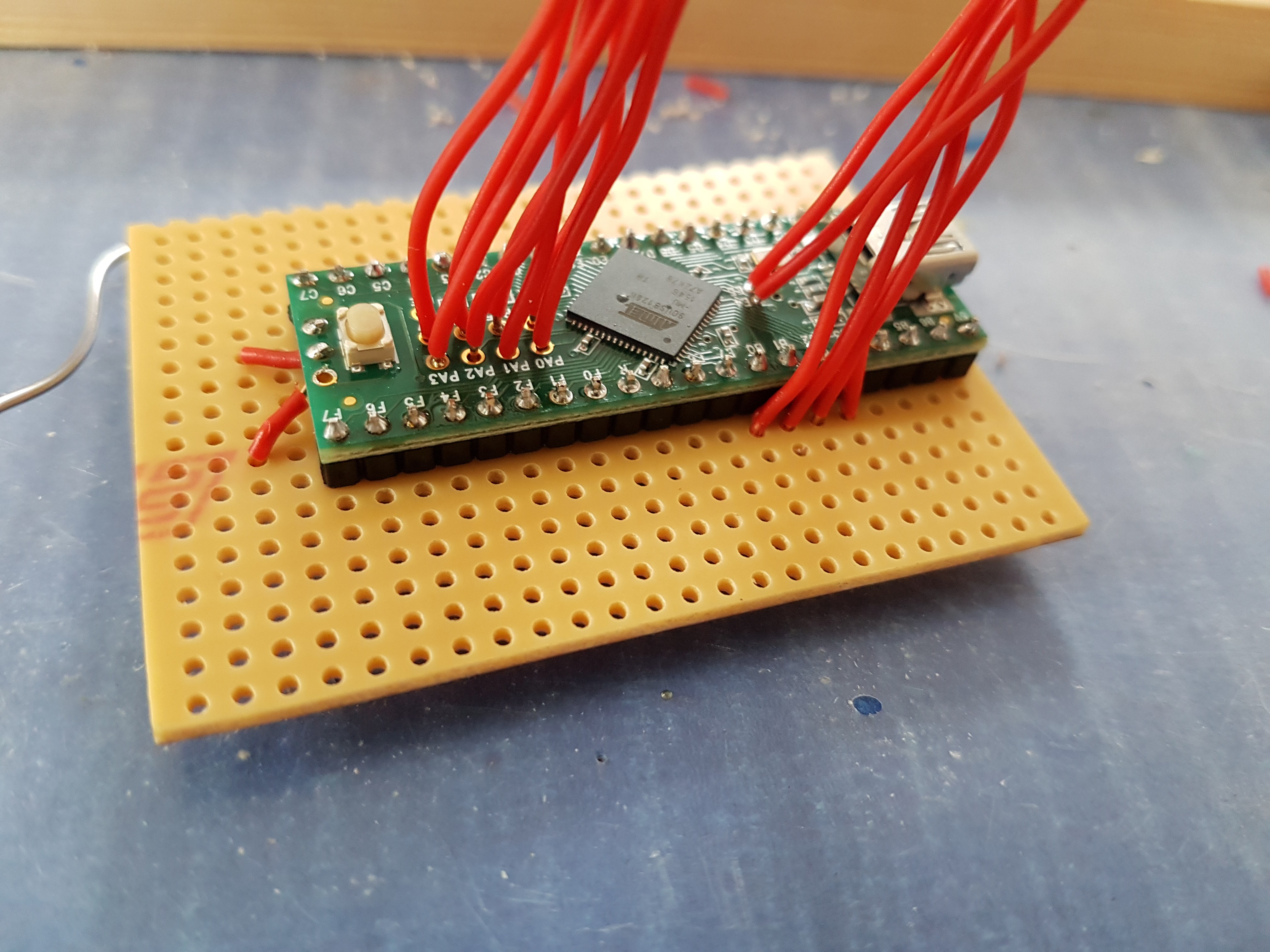
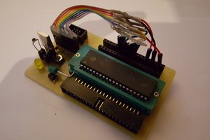
In our build we have 2 sub-boards each with 4 nodes - making a total of 8 nodes with a capacity for 320 i/o. Each sub board has it's own 5v 5 port switch, and a POE splitter - the whole board being run by 1 port on my POE switch.
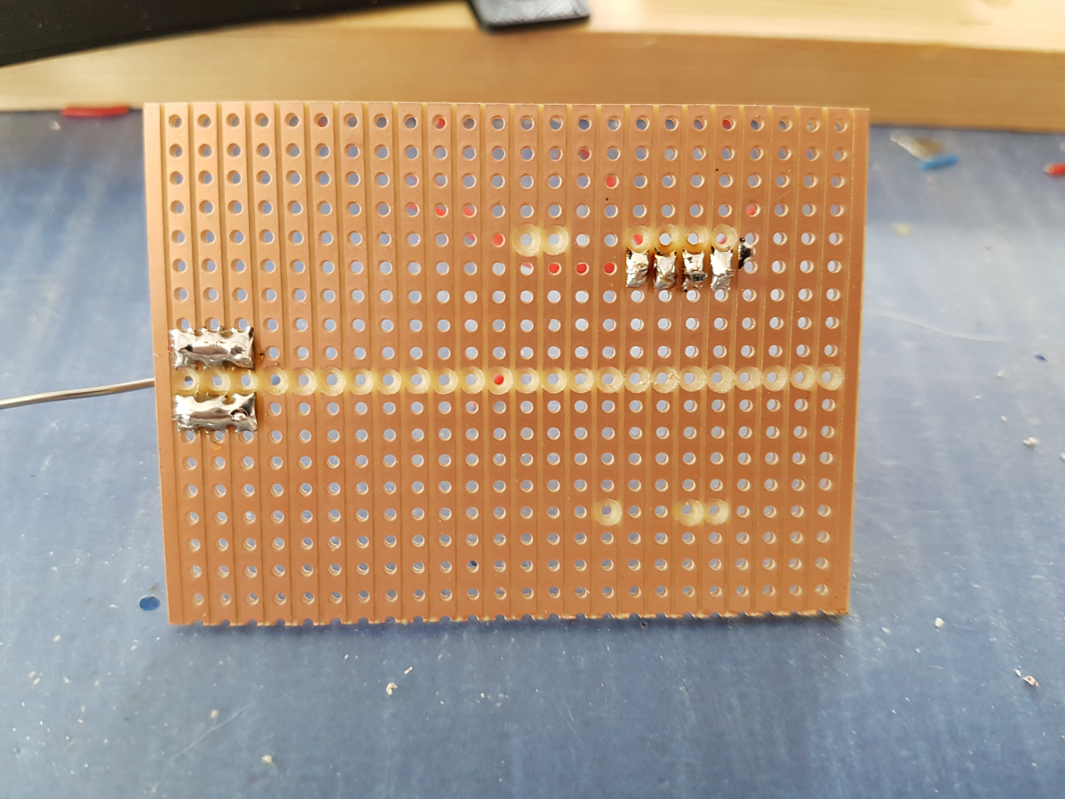
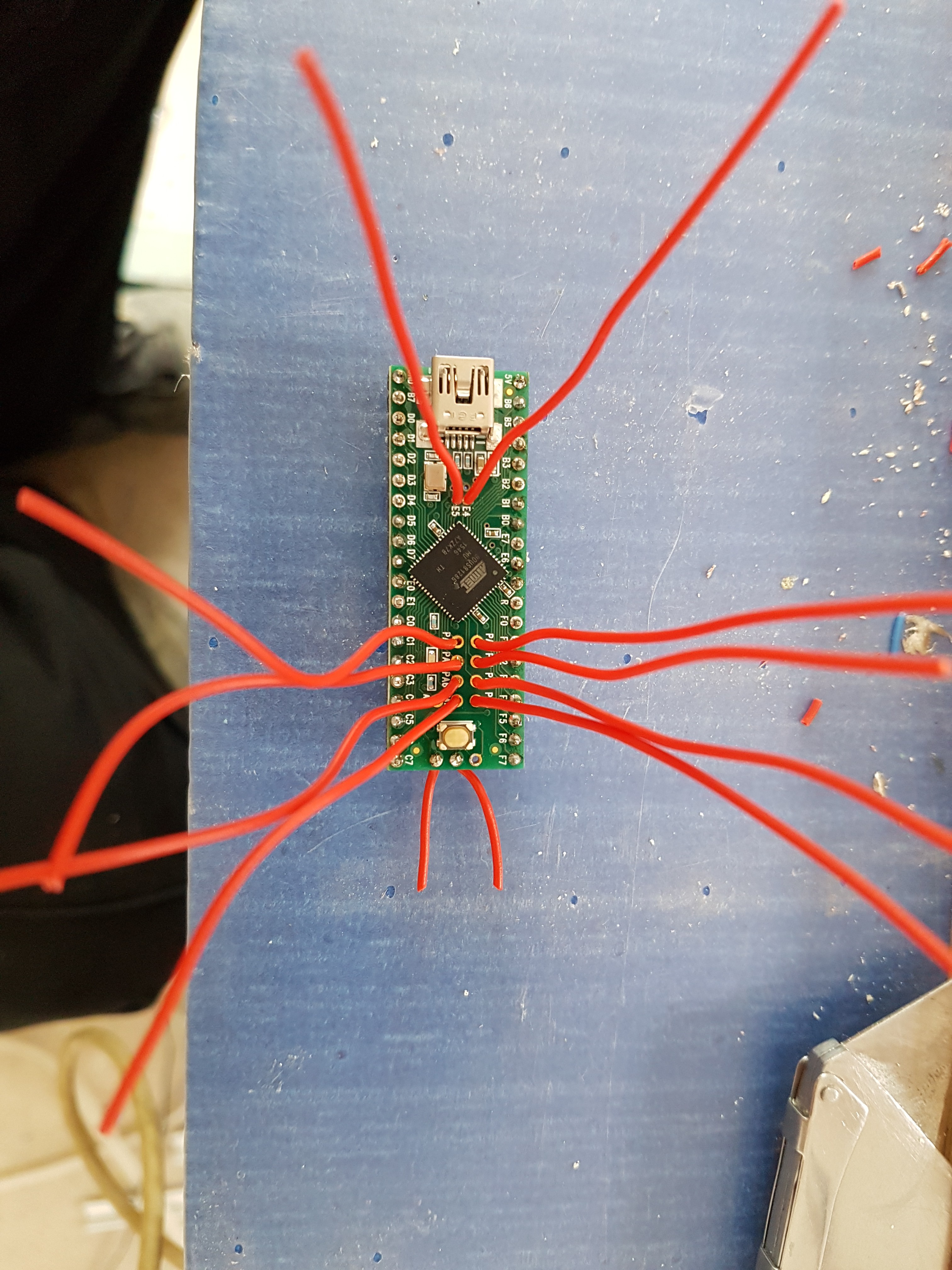
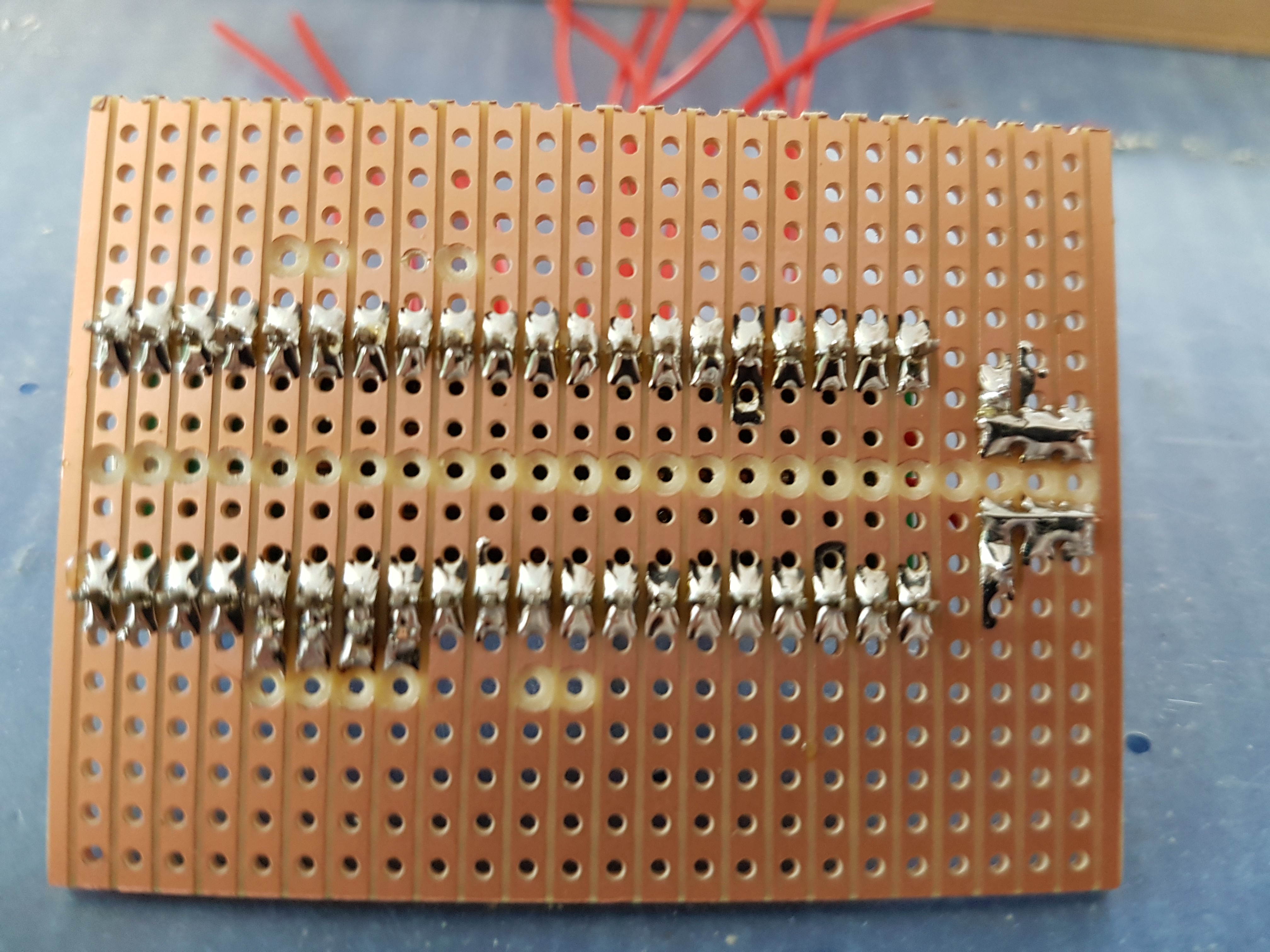
It was a challenge to get 40 I/O available on the teensy 2.0. We needed 4 pins for the ethernet connection & 1 pin for the on-board LED. Using the teensy's interior pins, and re-purposing one of the UART pins we were able to have 40 pins usable for io. The UART pin needed an external pull-up resistor to make it usable for normal io.

 Lumor
Lumor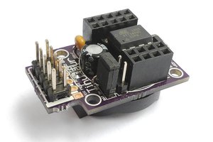
 Neven Boyanov
 Jon Thomasson
Hi. What wersion of Arduino IDE did you used? I have compilation error for Teensy ++2 board.