 Craig Bonsignore
Previously, I've built this project using an Arduino UNO + Adafruit Wave Shield + Macetech Chronodot + Sure Electronics 16x32 bicolor LED matrix + Fujitsu 4-wire resistive touchscreen.
Current goal: Smash the Wave Shield and Chronodot components into one Arduino-compatible shield, along with the connectors for the LED matrix and touchscreen.
Repo: All details on GitHub for anyone that's curious: https://github.com/cbonsig/openclock
Status: I've tried to translate the thru-hole Wave Shield components into their SMD equivalents, reroute created a schematic in KiCad, did a 2-layer board layout, OSH-Park'ed the board, assembled the components, and found three footprint snafus. So I've revised the schematic and BOM, and I'm working on the revised layout. Before I go crazy, this would be a good time for a peer review...
The BOM and Schematic are on a Google spreadsheet here:
Any comments or suggestions will be greatly appreciated! Especially for:
- the large capacitors (C4/C6C9) - would SMD aluminum cans be better?
- the LDO 3.3V regulator (U1) - not sure if this is a good choice, or if I need to worry about heat, or something else that I'm not thinking about.
- the opamp (U4) - I was guessing here, hope this is reasonable.
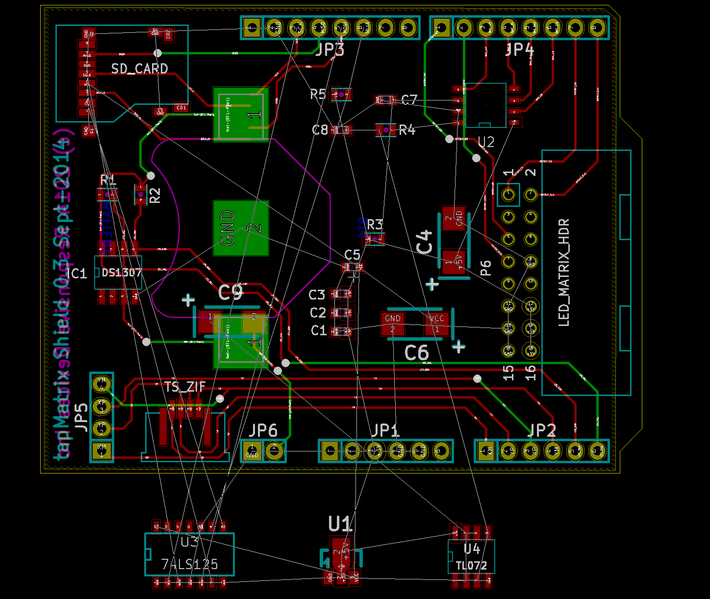
Finally, my torn-up layout this pictured below... Before I rearrange and reroute things, if there's anything else that I should think about, now would be a good time.
Discussions
Become a Hackaday.io Member
Create an account to leave a comment. Already have an account? Log In.