 Ian Hanschen
EvilMadScience was selling these on ebay earlier this year for cheap. I saw the ad and saw an FPGA, 30 led drivers, and 12 mosfets, with 1728 tightly packed RGB leds and my interest piqued. I pointed my friend Kevin at them and he bought out the rest of their stock to make a huge display. This is my knowledge repository for this board, based on some of my research, and a lot of help from Kevin Horton. I eventually did a lot more with this display, will need to post it later.

Reference (in progress):
Rework:
These displays, as with the 32x24 ones they are currently selling, have flaws and need to go through some rework. In my case, mine had some back rework done to it where a bypass cap was being resoldered, they killed the ground pad, so they soldered to a nearby via which happened to be for the top row red/green. You can see the result below.

What you can't see is that because I didn't know this and hadn't examined the board closely, the hot glue on the ATX connector is melting because of the amount of amps being pumped through due to a short. Basically, due to the action below both outputs on a dual output fet for the first row got shorted together, and the fet blew. I have since fixed the short, replaced the fet, and built a better power adapter.

Wow! I ended up desoldering all of this, cleaning the area with alcohol, and getting a good bond with the remainder of the destroyed ground pad with a new cap. 

It's easy to check for this if you take a continuity tester between pins 6 and 7 on each fet. My 32x24 board came in the same way - needing some rework, and in its case, some of the pins on the fpga are soldered together. It's important to check the whole board for things like the above, but also solder bonds between pins - check both sides.

It's possible that these boards can have a lot of burnt leds since they were returned for rework. The blue chip on one of the dice on my board is out. I haven't been able to source a and, because it looks like adaptive has custom leds made for their signs. I'll be sending my board to Kev to get it fixed. He's mastered reworking the leds on these boards and has spares.
Power

The power connector is a male 2x5 Molex MiniFit Jr plug. It has multiple inputs for 3.3, 5v, and ground, all of which must be used to avoid going over the amperage rating of the individual connector pins, the traces on the board, and the power cabling. I only wired 3 wires to the connector at first and the connector and the wires both got pretty warm. Don't make the mistake I did - Use all of the available connections.
The mated plug and crimps can be purchased from Digikey:
I just used an ATX power supply to try things out. I took a 24 to 20 pin conversion cable, and kept the 20 side and extracted the connectors from the 24 side, put the proper ones into a 10 pin minifit jr housing, and added a toggle switch for the PWR_ON. FYI, even though on an ATX case you can just tap the momentary switch to turn the power on, that is not how it actually works with the power supply itself. The motherboard just has some logic that uses the switch to close a circuit elsewhere (and open it if held for however many seconds is defined by the firmware on that board). I always thought it was a part of the ATX power supply itself. Kevin is using several of these cheap power supplies. 
Device Programming

There are pads for 2 10 pin headers on the board, outlined above (pin 1 in red). Both of these can be used with the Altera USB Blaster or compatibles. The JTAG allows for ICE stuff and quick configuration programming, whereas serial configuration EEPROM will configure the FPGA with its stored configuration at power up.
I soldered 2 2x5 headers onto these, but I have taken this board between home, my lab, and hackerbot a lot and unfortunately,...


 Ben Lim
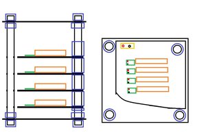
 cyplesma
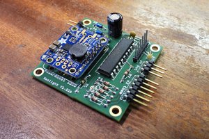
 robert
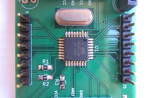
Looks like a bit of an issue with your photos in table cells.