 Paul Andrews
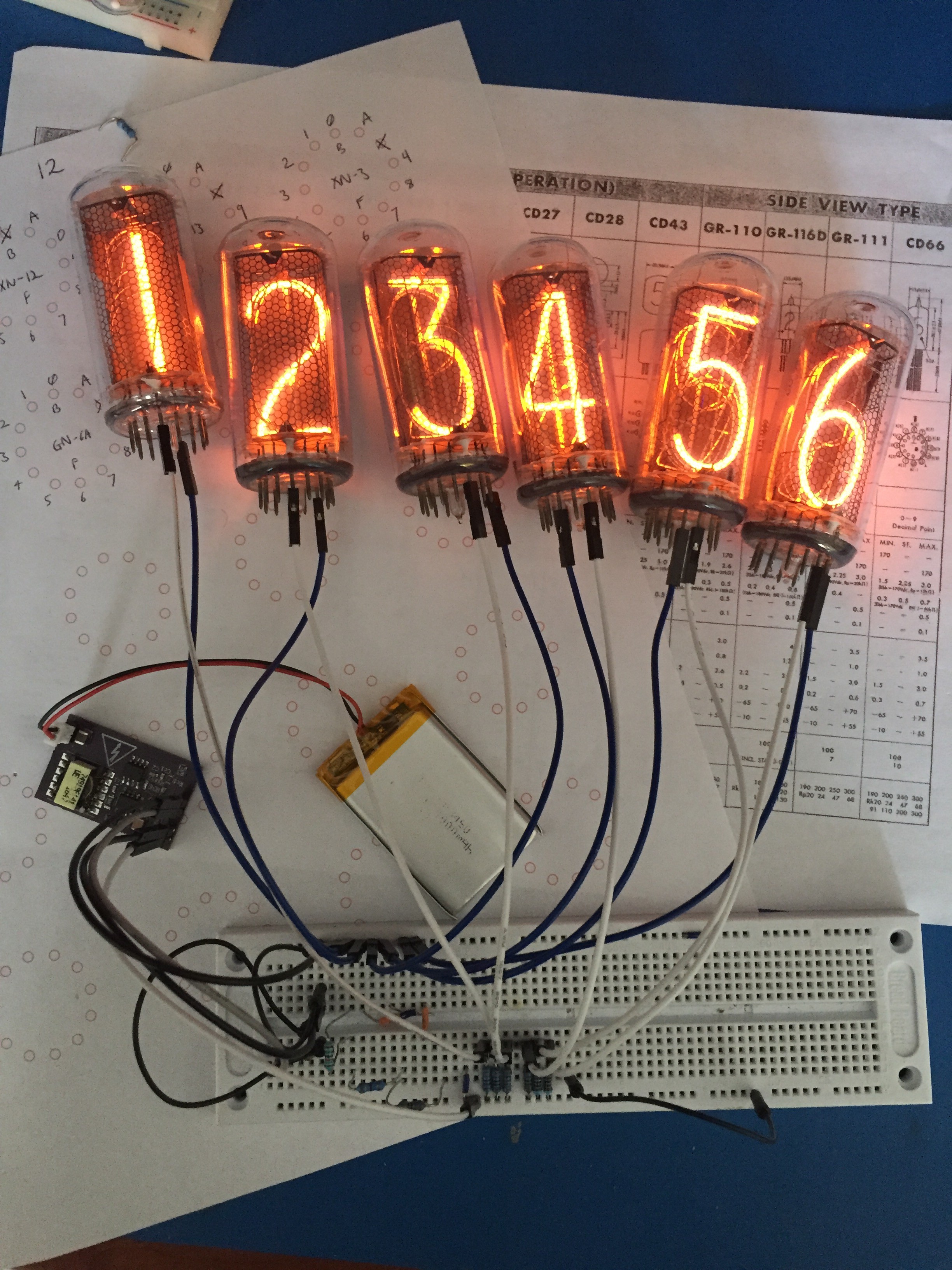
I'm documenting this retro-actively, so I'll be adding more project logs over the next few days/weeks. The first few iterations of the power supply are done. I ended up with a couple of variations on the theme, and I am still tweaking them to get the best performance out of them. I'll add circuit diagrams, parts lists and OSHPark links in due course.
I hope that others will be able to produce their own variations of this and will share them with the public. For me, I need to move on to actually using then in some Nixie clocks!
What seemed to be apparent from the outset was that my design should use a transformer. Nearly all of the power supplies I have seen are boost converters. These are quite simple in principle - at least using physical principles, not engineering ones. They rely on a collapsing magnetic field in an inductor to generate a voltage, the term I was taught for this was 'back-EMF'. To get it to generate more volts out than you put in, you want the field to collapse faster than you build it up. The power stays the same (well, obviously less because of losses in the system). So volts up, current down.
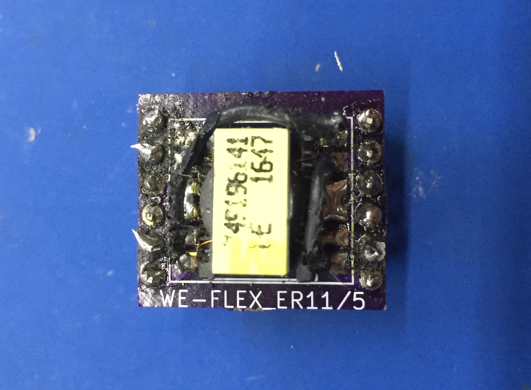
A single inductor can typically give you in the order of a 10x increase in voltage. It seems obvious that one way to go higher is to use a transformer. i.e. let the transformer boost the voltage generated by the back-EMF. Apparently, these are called flyback transformers. You can, quite literally, replace the inductor in a boost converter design with a transformer. At least in principle. Maxim have a great tutorial on this exact idea. 'Great', I thought, 'My search is over!'. Except that the transformers it uses just aren't available. In fact, it turns out, the transformer was going to be the biggest problem. Closely followed by everything else. But seriously, the transformer is the biggest problem. It seems like you can find a suitable inductor for a 12V-180V boost converter in a Chrismtas cracker. Suitable transformers are as rare as hen's teeth. Most people just make their own. That was a step too far for me. I'm too lazy.


 robert.c.baruch
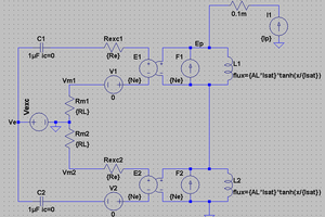
 jbb
jbb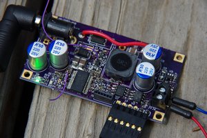
 Jonathan Bruneau
 Jakob Wulfkind
Personally, I just used an old iron type wall wart transformer backwards. 10's of kHz are not compulsory. (and I fed it from another transformer anyway. What is this "electronics" of which you speak?)