 Paul Andrews
It is time to address the ringing problem that we have seen in the simulation, and in the prototype. This analysis uses the AON6242 used in the original simulation.
The problem is that when the MOSFET turns off an oscillation in the drain voltage is initiated caused by the leakage inductance of the primary transformer winding and the output capacitance - Coss - of the MOSFET. The issue with this is that it can cause the peak voltage on the drain of the MOSFET to exceed the the rating - the ringing voltage can often be twice the reflected voltage, which is kind of unnecessary.
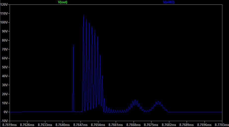
Here is a picture from the simulation showing the un-damped oscillations:
Here is what it looks like with some damping:
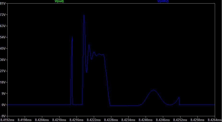
What you can see here is that the reflected voltage is around 40V. This is what the MOSFET should have to deal with. The peak voltage in this is down to 80V from 120V, which is an improvement, and the oscillations die out very quickly.
There are a couple of solutions. One is to clamp the voltage with a diode. Another is to dampen the oscillations with an RC (Resistor-Capacitor) snubber. Another solution is to do both. I chose to damp the oscillations with a snubber, because we also don't want the circuit to be radiating EMI, so dampening the oscillations is a good thing to do anyway. I chose the topology in this application note. I started by setting the capacitance (Csnub) to 2xCoss. This halves the frequency of the ringing. The resistor value is set to:
With LTSpice we can measure the ringing frequency as follows:
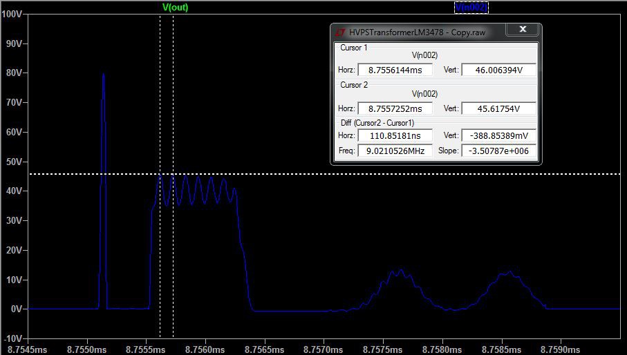
So the frequency is 9MHz. From the datasheet for the AON6242, Coss is 540pF, so Csnub is around 1200pF. This gives an Rsnub of 15Ω.
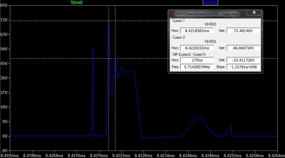
You can see that the frequency has approximately halved in this image:
We can damp the ringing more by increasing the resistor value, but this will dissipate more power. According to LTSpice, the RC snubber dissipates this much power:
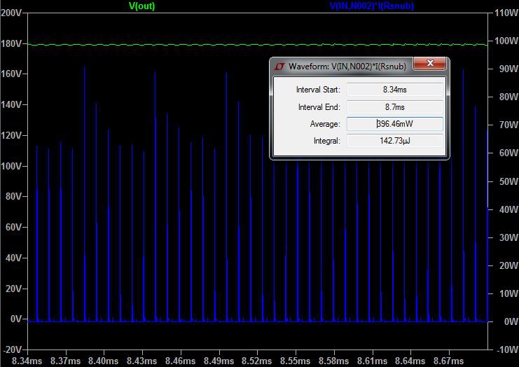
About 0.4W. This is quite a lot, so I am left wondering if there is a better way to do this, or even if it is necessary at all.
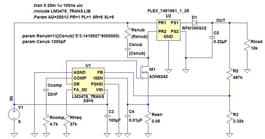
The whole circuit now looks like this:
Here is what I measure with the actual prototype with no snubber (remember this uses an IRL640A, not an AON6242):
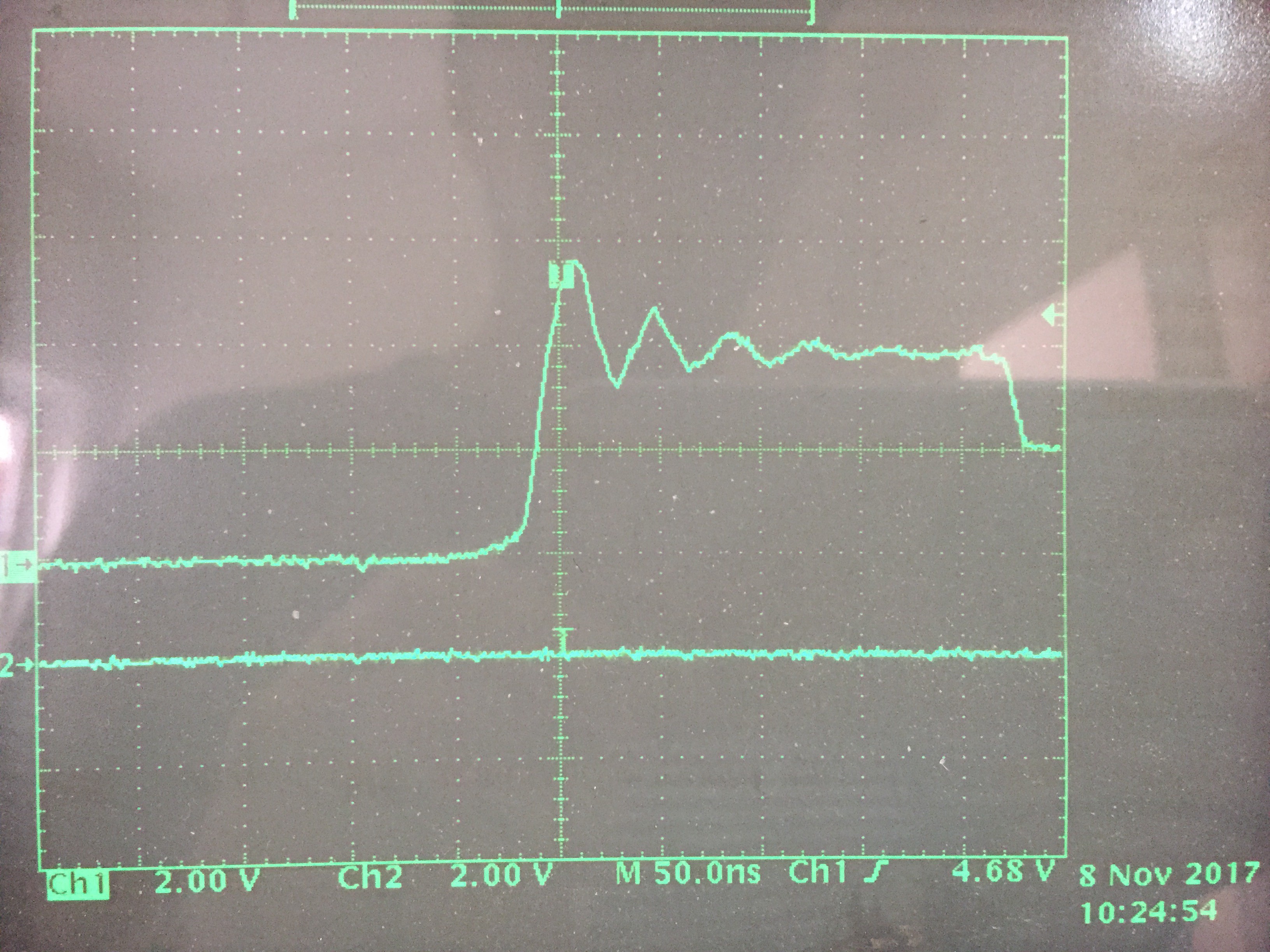
Note that channel one has a 10x probe, so each square is actually 20V. We can see that the peak is only around 60V, so there is no real need for a snubber here, but we will continue just to test it out. Note that the frequency of the ringing is 1/50ns or 20MHz. Coss for the IRL640A is only 200pF, so we only need a Csnub of 400pF, and our Rsnub is now 20Ω. Here is what it looks like after applying the snubber:
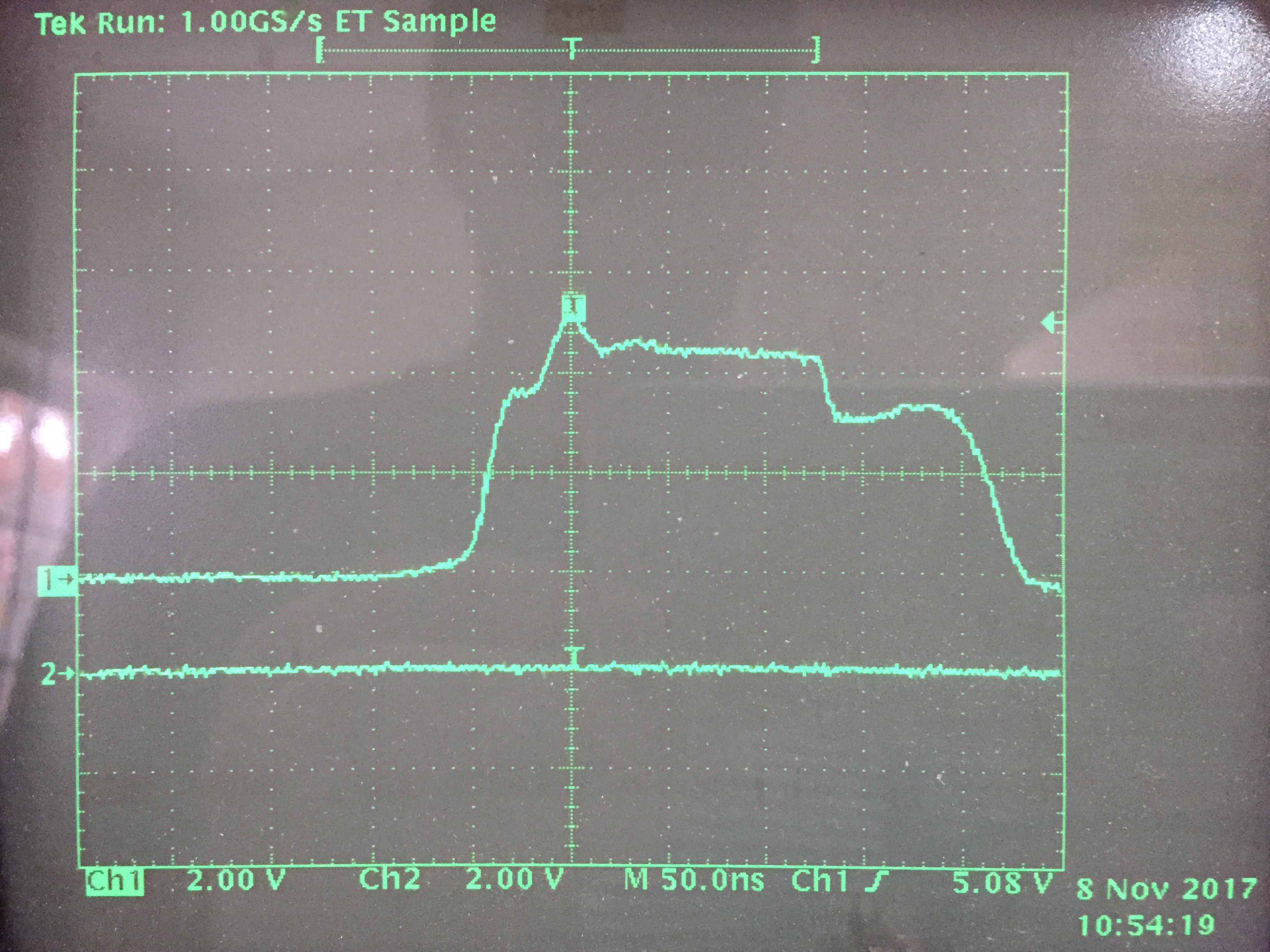
So yeah. It's damped. Seems a bit unnecessary with this prototype, but I will leave it in the circuit when I have some actual PCBs fabbed - I can always leave it unpopulated, but I can't add it after the fact.
BTW, I re-ran the simluation with the IRL640A, and the frequency of the ringing is very similar: 17MHz.
Discussions
Become a Hackaday.io Member
Create an account to leave a comment. Already have an account? Log In.