 Paul Andrews
For the final design, I also wanted to be able to provide a means to enable/disable the power supply and vary the output voltage.
Enable
Enabling/disabling the power supply is necessary if we want to implement tube blanking:
- We can turn the nixie tubes on or off based on a schedule. This is typically done to extend the lifetime of the tubes.
- In a battery powered clock, we only want the tubes on when the user is actively looking at the clock, otherwise we will run out of battery pretty fast.
Note that this is not used for dimming the display - we don't want to turn the entire supply on and off really fast. This is better done using direct control of the current flowing through the tubes themselves.
The LM3478 already has an enable pin, so we can use that in our design.
Voltage
Varying the output voltage is handy for several reasons:
- At low input voltages, the power supply is more able to regulate itself if the output voltage is also lower.
- Other applications of the power supply might require a different output voltage.
There are a couple of solutions to varying the output voltage, but the one that I went for is explained in an article by Simon Bramble. This solution provides several benefits:
- It enforces a limit on how high the voltage can go.
- It allows us to vary the voltage from zero to that limit.
- It allows us to control the voltage using PWM from an MCU.
- It doesn't require a potentiometer on the board itself.
It has some drawbacks too:
- It requires more breadboard wiring to set the output voltage. An on-board potentiometer would provide a simpler solution.
If the design is integrated directly with a clock - rather than being a separate power supply board - you could just set the voltage to whatever you need directly.
Anyway, this is the basic resistor setup that I will be using. R1 and R2 are already part of the design. The new part is R3 to some voltage Vset. We also add Radj in series - R3 will be fixed:
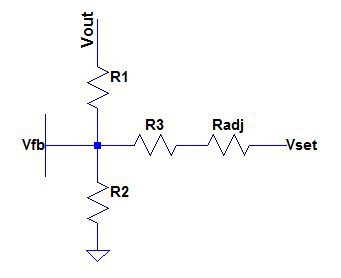
So, directly from Simon Bramble: The current flowing through R1 plus the current flowing through R3+Radj must equal the current flowing through R2, because no current flows into Vfb. So we have (folding Radj into R3 for now):
In our case Vfb is 1.26. If we substitute that in and re-arrange for Vout, we get:
The first term is just the regular equation, without R3 and Vset. The second term shows the effect of including R3 and Vset. For now, let's assume that Vset and Radj are zero. It is clear that as R3 increases, the effect of the second term is lessened. At the limit, if R3 is infinite, the second term has no effect at all. As R3 decreases in size, the second term adds to the value of Vout. If R3 is is zero, we are in trouble, so we must choose some minimum value for R3.
If we allow Vset to increase, we can see that the second term reduces the value of Vout. The lowest value for Vout is zero. I will arbirtrarily choose 5V to be the highest value of Vset, because it is a common logic level. So we want Vout to be 0V when Vset = 5V.
Further, to make things simple, I will arbitrarily choose R2 to be 10K. This is what Simon did, and it as about right if we want R1 to be large (which we do). So, now we have two equations:
And
Equating the two, we get:
Or:
Plugging back into the first equation, we get:
- R3 = 30K
- R1 = 1,200K
Because of the voltage rating of regular resistors, we will use two resistors in series for R1 of around 600K. The nearest standard one is 604K, so R1 will be 1208K. Because this is slightly higher, we will use a 10.2K resistor for R2 to compensate. So we have:
- R1 = 1,208K
- R2 = 10.2K
- R3 = 30K
If we plug these numbers back in to our equations (using a spreadsheet, it is way easier), we get:
- Vset = 0V, Vout = 201V
- Vset = 5V, Vout = 0V
- Vset = 2.5V, Vout = 100.5V
- Vset floating, Vout = 150V
We can adjust Vout anywhere in between by adding Radj. e.g. with Radj = 20k
- Radj = 20k, Vset = 0V, Vout = 181V
- Radj = 20k, Vset = 5V, Vout = 60V
- Radj = 20k, Vset = 2.5V, Vout = 120V
Etc.
It was slightly before this, that I realized that this is exactly what John Taylor did with his power supply, even down to the resistor values. I honestly didn't reverse-engineer his power supply! It was basically driven from Simon's design and the fact that Vfb is almost the same on the chip I use and the chip that John uses.
So now, the circuit looks like this:
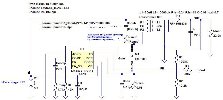
You may notice that the MOSFET is yet another model: An IRL3103, and that there is a different transformer symbol. That is because I was modelling the circuit for a different transformer.
PWM Voltage Control
To control the voltage using a PWM signal we need to build an RC filter to smooth out the oscillations. In the image below we have set up a 5V source with a PWM frequency of 16KHz and a 50% duty cycle. We have added an RC filter with a a cutoff frequency of about 1/4 that:
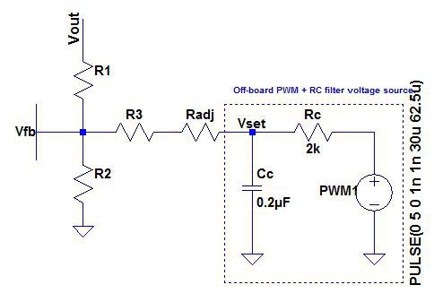
Cutoff frequency of the RC filter is given by this equation:
Here are the results of a simulation for that:
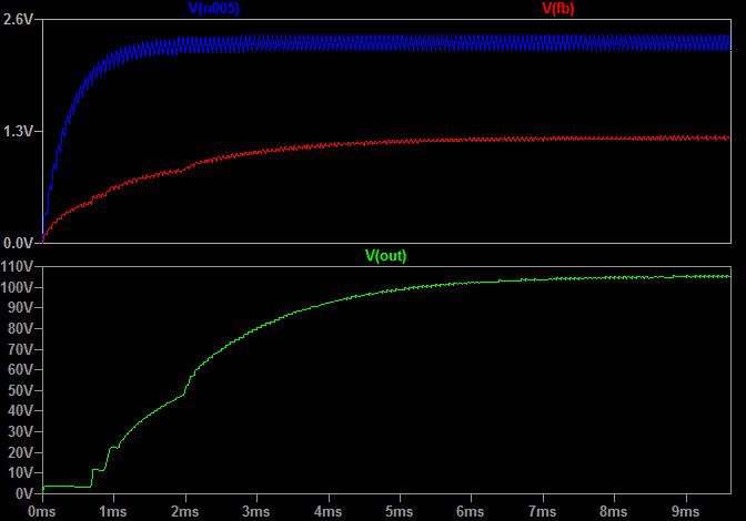
Note that Vset (Vn005 in the graph) comes out at around 2.3V, so Vout is correspondingly higher at around 105V.
Discussions
Become a Hackaday.io Member
Create an account to leave a comment. Already have an account? Log In.