Close
0%
0%

Library files of LPC2148 for HUB75 Based RGB Panel

Library files of LPC2148 for driving graphics in HUB75 based RGB LED panels

Similar projects worth following
Advertisement is used to promote or publicize a product, service, or event in a public medium. In many cases advertisement boards are prepared using RGB LED panels. We intend to make this process easier by designing library files of HUB75 based RGB LED panels for LPC2148 microcontroller which is based on ARM7 CPU.
User should be able to generate any text or pattern using the library files created by calling suitable functions. User will be able to choose number of panels, size of panels (16x32 or 32x32 etc.), pixel location, brightness and color of LEDs.
High frequency output at almost 50 MHz will be given to the RGB LEDs in an interleaved and cyclic fashion.
The RGB LED Panels can be also be used to generate still and interactive images and videos as well as games. The pattern generation can be coupled with on-board switches, led and various other peripherals.

 Overview

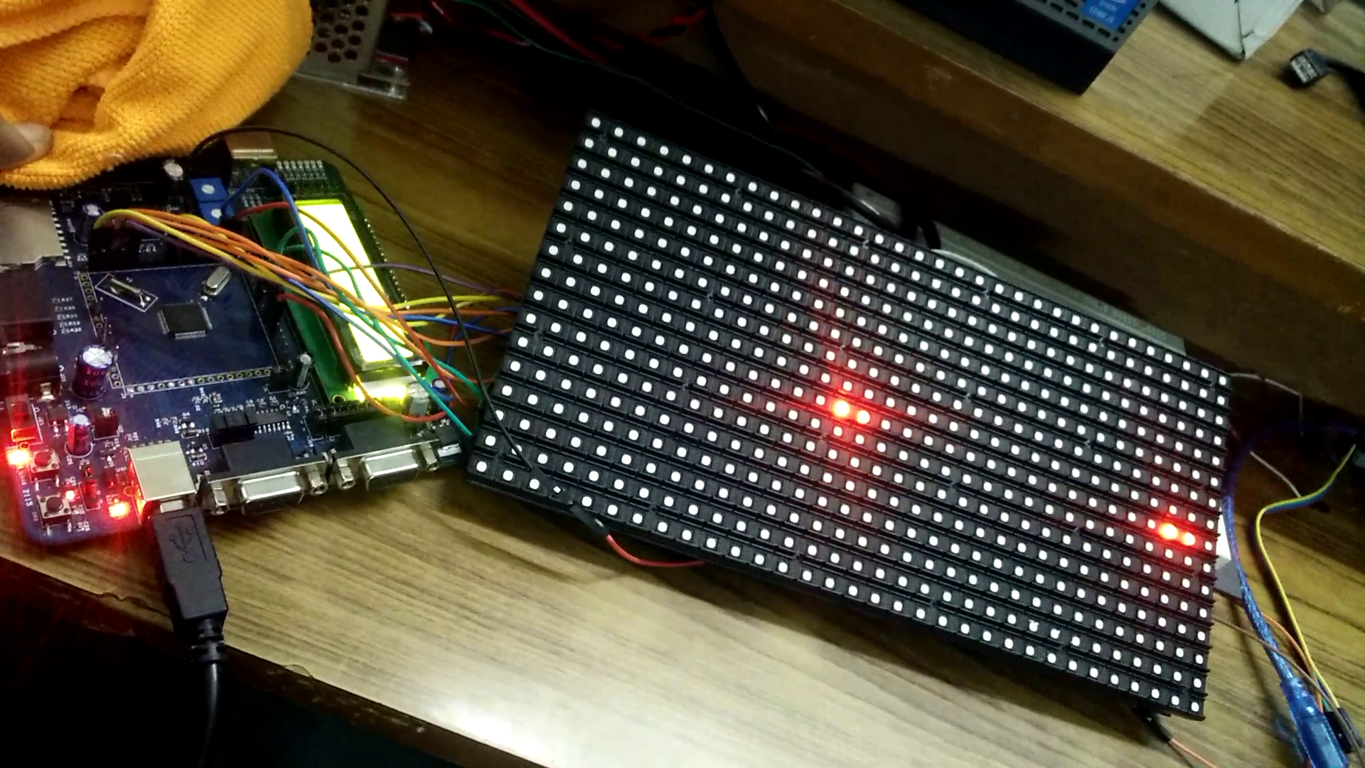
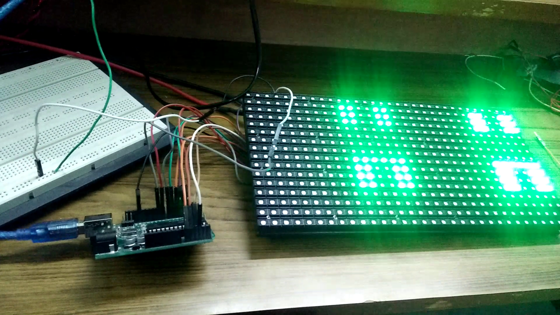
RGB LED matrix panels are used in commercial purpose such as advertising or to make video walls etc. We have used a HUB75 based 32x32(1024 LEDs) RGB LED panels in this project. This panel has 1/16 scan i.e. at a time 2 rows are selected for a given address.

Power Requirement

These panels require good 5V power supply, with at least 5A current capability. This panel running full tilt (all pixels set white), draws nearly 4+ Amps of current.
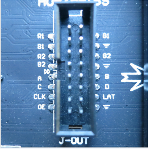
Pin Description

There are total 16 pins, 6 pins for R, G, B value, LATCH, OE, CLOCK, 4 pins for address selection and 3 pins are ground.

How the Matrix Works

  • There are 1024 RGB LEDs in a 32x32 matrix. But all 1024 LEDs cannot be driven at once.
  • One reason is that would require a lot of current, another reason is that it would be really expensive to have so many pins.
  •  Instead, the matrix is divided into 16 interleaved sections/strips. The first section is the 1st 'line' and the 16th 'line' (32 x 2 RGB LEDs = 64 RGB LEDs), the second is the 2nd and 17th line etc. until the last section which is the 15th and 32nd line.
  • The reason they are arranged it this way is so that the lines are interleaved and look better when refreshed, otherwise we'd see the stripes more clearly
  • For a single pixel to glow we have to feed 16 bits of data (4 bits for each R, G and B).
  • The controller (say an FPGA or microcontroller) selects which section to currently draw (using A, B, C and D address pins – 4 bits can have 16 values). Once the address is set, the controller clocks out 32x2=64 bits of data and latches it. Then it increments the address and clocks out another 64 bits, etc. After doing this for four times the address is incremented. So the sequence in a nutshell is as below…
  • Feed the rows
  • Disable OE
  • Enable Latch
  • Increment address
  • Enable OE
  • Disable Latch
  • The only downside of this technique is that despite being very simple and fast, it has no PWM control built in! The controller can only set the LEDs on or off. So what to do when we want full color? We actually need to draw the entire matrix over and over again at very high speeds to PWM the matrix manually. For that reason, we need to have a very fast controller, here we have used 60 MHz frequency to drive the panel.

Schematic.png

This file contains the schematic.

Portable Network Graphics (PNG) - 124.30 kB - 11/29/2017 at 15:33

Preview
Download

hub75.c

This file contains some functions at their finality and incompleteness as programming is a continuous process a lot can be a tinkered with.

C Source File - 10.81 kB - 11/28/2017 at 18:40

Download

hub75.h

This file contains global variables and functions.

h - 1003.00 bytes - 11/28/2017 at 18:40

Download

main.c

This file contains a pattern for showing various colors. "activatepanel()" function needs to be in a while function. If not VICIntClr line has to be deleted from ""hub75.c.

C Source File - 1.37 kB - 11/28/2017 at 18:40

Download

  • 1 × 5V power supply with high current
  • 12 × connecting wires
  • 1 × RGB LED Panel
  • 1 × LPC2148 Microprocessors, Microcontrollers, DSPs / ARM, RISC-Based Microcontrollers

  • Current pattern video

    palpoulami11/28/2017 at 19:48 0 comments

    The video contains library files to drive an RGB Panel on LPC2148.
    In this video we see a pattern where the blocks change color with time to showcase a capability of the panel to generate color.
    Please note that the lines were generated due to some camera issue and were not visible with naked eyes.

  • Pattern in main function

    palpoulami11/28/2017 at 19:38 0 comments

    The pattern brings up blocks of colors with time of various colors shown below.

    The lines are not visible via naked eyes.

  • Making Headers

    palpoulami11/28/2017 at 18:37 0 comments

    Following functions were created:

    void activatepanel(void);
    void initClocks(void);
    void initTimer0(void); 
    void setupPLL0(void); 
    void feedSeq(void); 
    void connectPLL0(void);
    void GPIO_Init_FAST(void);
    void timerSettings(void);
    void initializepanel(void);
    void latch(int);
    void setbitplane(int,int,int,int,int);
    void drawpixelinit(void);
    void drawpixel(int,int,int,int,int);
    void drawverline(int,int,int,int,int,int);
    void drawhorline(int,int,int,int,int,int);
    void drawrect(int,int,int,int,int,int,int);

  • Drawing a pixel

    palpoulami11/17/2017 at 16:47 0 comments

    __irq void timer0ISR(void){
      long int readVal;
    if(pixel<256){
    if(pixel<3)
    FIO0SET = 0x00040000;   //rgb
    else
    FIO0CLR = 0x00FC0000;   //rgb
    FIO1SET = 0x00010000;   //clock 1
    FIO1CLR = 0x00010000;   //clock 0
    if((pixel==31)||(pixel==63)||(pixel==95)||(pixel==127)||(pixel==159)||(pixel==191)||(pixel==223)||(pixel==255))
    latch();
    }
    else pixel=0;
    pixel++;
    readVal = T0IR; // Read current IR value 
    T0IR = readVal; // Write back to IR to clear Interrupt Flag
    VICVectAddr = 0x0; // End of interrupt execution
    }

  • Running current files

    palpoulami11/17/2017 at 16:18 0 comments

    Running the LED panel on Arduino with library present in on the internet.

    Scrolling "H" in a loop.
    Does not work as per the video present in the link http://www.instructables.com/id/Arduino-UNO-Based-HUB75-LED-DISPLAY-DRIVER/

    Learning:

    Arduino

    Inline assembly code

View all 5 project logs

  • 1
    5V power supply

    It needs 5V power supply with upto 10 Ampere current supply.

    Glowing a single pixel will result in 1-2 Ampere current consumption.

View all instructions

Enjoy this project?

Share

Discussions

Similar Projects

Does this project spark your interest?

Become a member to follow this project and never miss any updates