We all know that it's really fun to build a microcontroller project that has music or some sort of thing that are ear-catching.
And especially in the festive seasons, some of us are inquisitive enough to pick up the microcontroller programmer and a couple of electronic components and whip up a contraption so that we are making the season more fun and enjoyable.
However, generating audio on a microcontroller is a very big hurdle. You may need to know well about:
1.) Hardware (electronic components)
2.) Software (signal processing and optimization)
And finally, a lot of reading and trial-and-errors. There is no "one-size-fits-all" solution.
So where are we? Yeah, let's start with this case study.
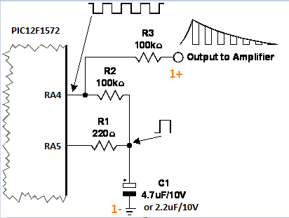
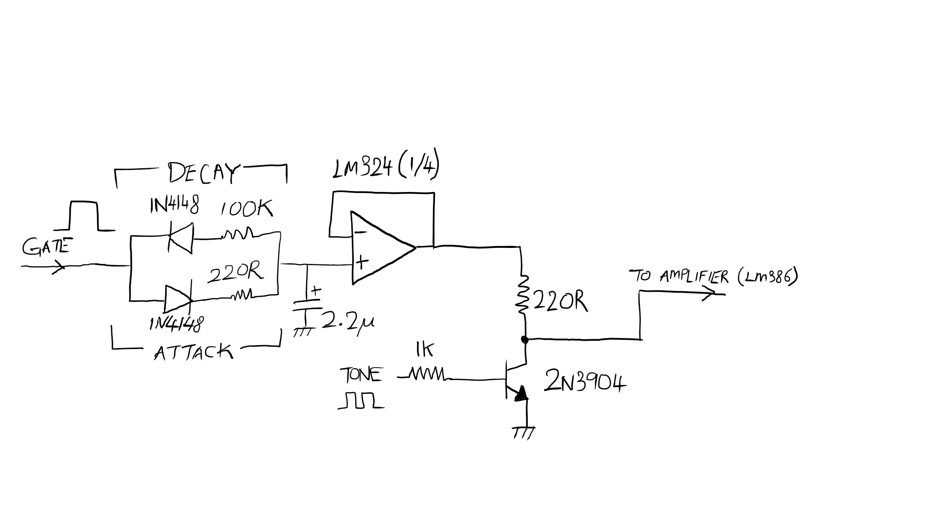
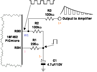
It all started in late 2009 when I chanced upon this website (in the project page) about the PIC18F microcontroller that generates three channels of square waves, with a decay-envelope on each channel. A lot of trial-and-error and mindless experimentation lead me to this : the thing works, but required a lot of changes to the original schematic. This thing survived in a Christmas decoration (for two Decembers) that is partially inspired by the Myke Predko's Programming and Customizing the PIC Microcontroller book.
The most unfortunate part was, I did not write that down, and being deeply unsatisfied with the circuit, I took the components down and replaced it with a WAV player.
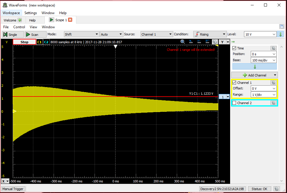
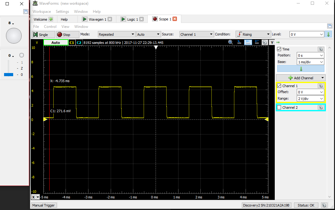
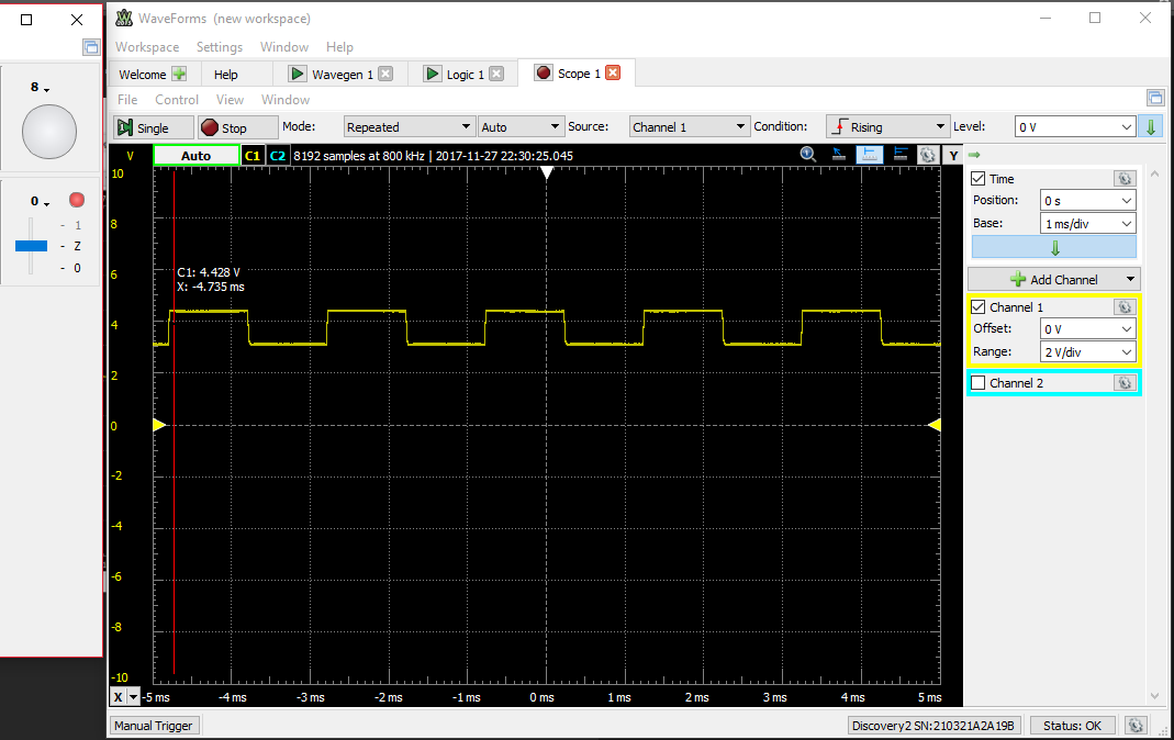
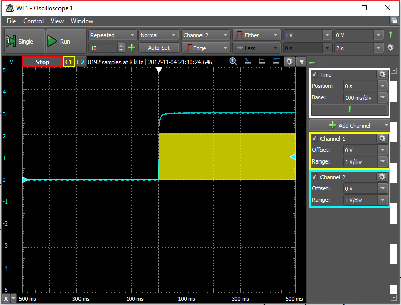
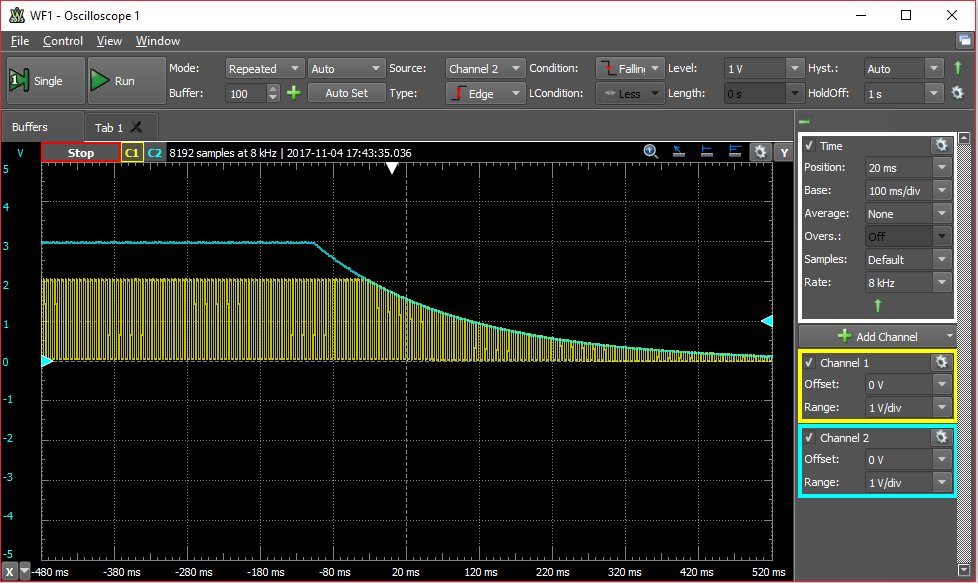
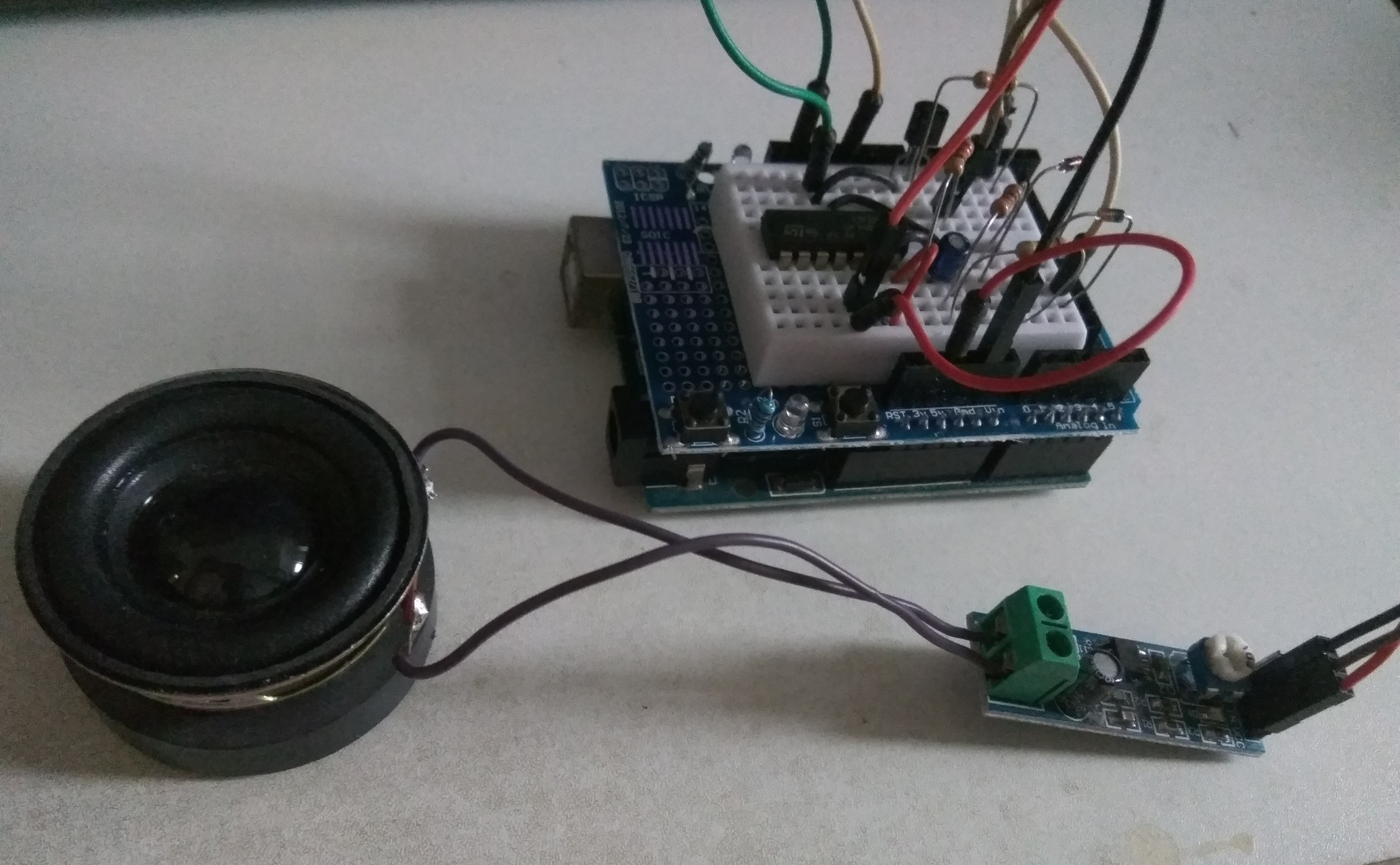
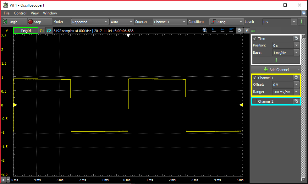
Here I am again, with the Analog Discovery 2, and trying to reproduce that part of the project. Did it work? Should I mess around with it some more? Or should I ditch it and rework it with a different set of components? Here I go! :)
Note: The archived webpage with the schematics and other pictures intact are inside the file list, in PDF form.
 Emilio P.G. Ficara
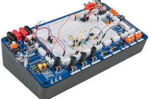
 Just Me NL
 Eric Herbers