 Christian Walther
So far my experiments had used image data produced by hand in Photoshop. The goal is to have this completely automated, so that a visitor has their picture taken by a webcam and gets a live preview as far as possible, and upon a button press the system spits out a DXF file ready for import into the plotter software (Silhouette Studio).
The algorithm to transform a camera image into two channels for luminance and color accent that I had in mind was as follows: Treat the pixels of the image as a point cloud in the RGB color cube. Throw away the darkest points (background), and with the rest perform a principal component analysis, i.e. find the direction along which the point cloud has the largest extent, the direction perpendicular to it with the second-largest extent, and perpendicular to the two the direction with the smallest extent. The direction of largest extent will usually be something in the general direction of overall brightness, as every portrait has light and dark parts, and projecting the image onto it should yield something suitable for the luminance channel. Perpendicular to it, the direction of second-largest extent corresponds to the largest variations in hue and should be suitable for the color accent channel. Depending on whether it points in a more reddish or more greenish direction, red or green can be chosen for the output color.
The principal component analysis involves diagonalizing a matrix, and I suspected that doing all this number crunching in real time would require writing the software in a language that compiles to machine code. So I went looking for C or C++ libraries that would allow me to capture images from a USB webcam in a platform-independent way. (For now the software would only need to run on my Mac, but later on trying it on my CHIP (Linux) would be nice, and once published someone else might want to run it elsewhere.)
I found two such libraries: libuvc and Video Capture. I first tried libuvc. Building and installing was straightforward, and once I chose suitable format and frame rate settings, the included example program seemed to successfully turn on and capture frames from both the internal camera of my MacBook Pro and the cheap 640x480 USB webcam I had bought from Conrad for this project. However when I added code to output the captured frames, it seemed that I was only getting random garbage instead of a camera image. I considered debugging that, but that would have required spending time learning about how USB cameras work, which was precisely what I was trying to avoid by using a ready-made library, so I abandoned libuvc.
Before trying the other C++ library, I decided to give Processing a try, since a recent exhibit in the MuDA had reminded me that it supported webcams. Maybe JIT-compiled Java wouldn’t be that much worse at number crunching than compiled C. Indeed getting at camera pixels turned out very easy using Processing’s Video library.
I had a vague recollection that the pricipal component analysis involved diagonalizing the covariance matrix, and for that I first tried to refresh my own knowledge of linear algebra, but then discovered that a web search would take me directly to the destination, in the shape of a research paper comparing different methods that came with ready-made C code. I chose its analytical method (dsyevv3) because of its reported performance advantage and because its shortcomings did not seem relevant to my case, and translated it to Java, which mainly involved some search-and-replace processing to expand macros.
Implementing my algorithm with this was then straightforward and, lo and behold, it still performed in real time. Processing therefore seemed the way to go. Adding a histogram of the point cloud in the red-green plane with the found principal component vectors overlaid confirmed that the code was doing what I expected it to.
I had suspected before that to get interesting images I would need red and/or green colored lighting from different directions than the neutral main light. To test this, I did some experiments with a piece of NeoPixel (WS8212B) LED strip connected to a WEMOS D1 mini running MicroPython, programmed to alternatingly light four LEDs (few enough to safely drive off a USB port) red and green. Indeed when photographing just my face with no brightly colored clothing parts in view, the colored lighting from the side increased the second principal component and often made for a recognizable color accent in comparison to the more or less random tinting without it.
A small tweak turned out to improve the choice between red and green as the accent color: Instead of choosing the sign of the second principal component vector such that it pointed away from black, choose it such that the vector has a positive component in the direction (red or green) that is more prevalent in the average color of the image. This made it more consistently choose green when the lighting was green and vice versa.
The two-channel image generated from the two principal components could already be displayed in gray/red or gray/green to give a rough preview, but I still wanted something closer to the final line drawing, to give a better impression of the detail resolution. Generating the actual final drawing in real time was out of the question, as running the procedure in Octave took up to several minutes, depending on the number of lines it had to place. Instead, I decided to use a fixed regular grid of straight, parallel line segments of the correct dimensions, arranged in a brick wall pattern, of which each one could be present or not. Finding which ones should be present then amounted to a halftoning problem as if reducing a grayscale image to black and white pixels, only that my pixels were not squares on a square grid but oblong rectangles on a brick wall grid. Common methods for high-frequency halftoning are error diffusion and ordered dithering. Error diffusion seemed like it could get messy on my non-square pixel grid, but something like ordered dithering should be applicable. I devised a method that covered a unit cell of a 10-by-10 pixel square grid of input with 12 diagonal line segments, each taking input from its 4 most covered pixels (which means that it still discarded 52 of 100 input pixels, but that shouldn’t matter much for my mostly continuous input images), and ordered them in a sequence that made for a nice dithering pattern. Applying this independently to the two channels, with line segments rotated 90°, and overlaying them in the proper colors generated a preview image that should be more representative of the final drawing, and still ran in real time. The hope is that, despite matching line sizes, the final drawing should have even better resolution because it can place the lines adaptively, but that has not been tested yet.
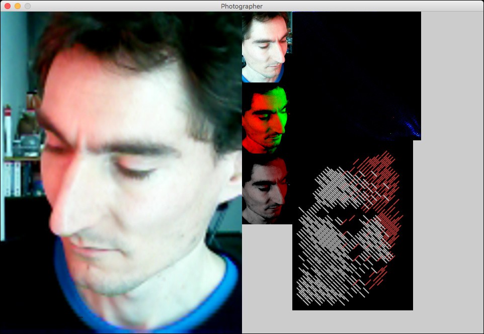
Screenshot of the Processing application: left: flipped camera image; middle: cropped camera image, two-channel image (luminance red, color accent green), silver/red preview; right: point cloud (red down, green right, mean = red dot, first principal component from red to yellow dot, second principal component from red to green dot), line drawing preview
This post concludes catching up with history! What has been described so far is the current state of the project.
Discussions
Become a Hackaday.io Member
Create an account to leave a comment. Already have an account? Log In.