 Saabman
Specifications
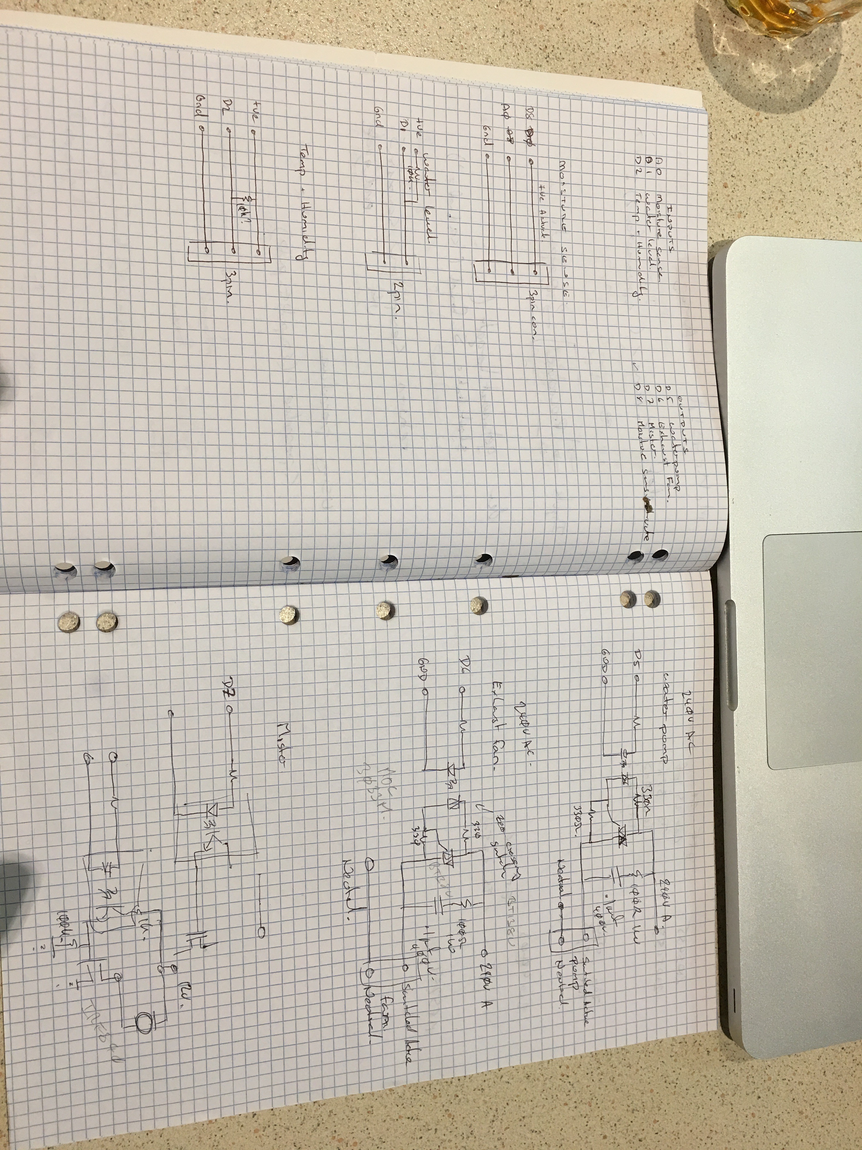
- Inputs
- Grow media moisture (analog, input 0-3V)
- Humidity (digital, one wire bus)
- Ambient Temperature (digital, one wire bus)
- Water storage level ( digital, float valve)
- Outputs
- Water Pump (240V AC 200W)
- Exhaust Fan (240V AC 100W)
- Mister (12V Solenoid 10W)
- Connectivity
- Remote data viewing via mobile phone
- Remote parameter alteration
Background
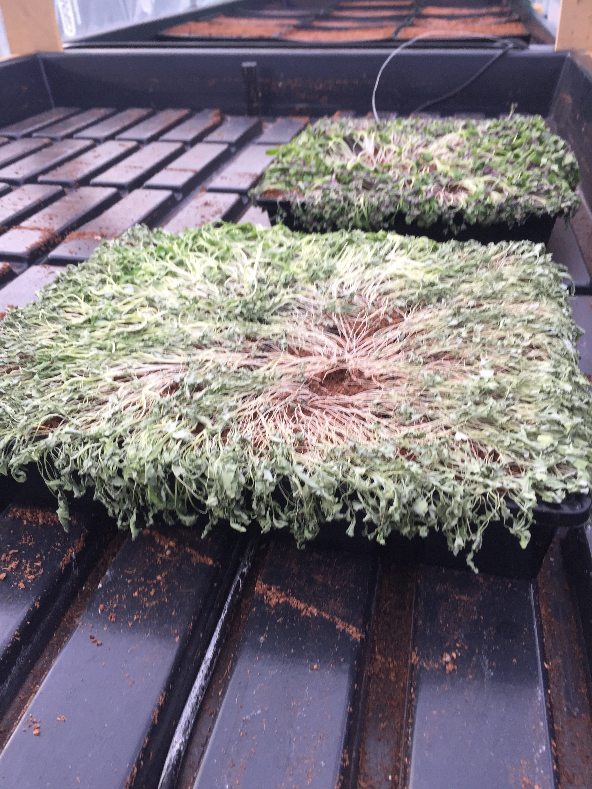
In the current configuration the grow bed is flooded by running a pump for 6 minutes a timer than turns the pump off for a period of time which allows the grow bed to drain and then the cycle is repeated.
This current arrangement does not allow for any variation in environmental conditions and variations in the moisture uptake transpiration of the plants throughout their life cycle.
Operation
Moisture
The proposal is to monitor the moisture level of the grow medium and when the moisture level drops below a preset level the pump will be activated to flood the bed. Once the bed has flooded the pump will be switched off and the bed allowed to drain.
Temperature
The temperature of the green house will also be monitored if it raises above a predetermined level an exhaust fan will be activated to expel the hot air and draw fresh air in.
Humidity
In conjunction with the temperature monitoring the humidity will also be tracked and adjusted through the operation of the exhaust fan or misting sytem.
Proposal
It is proposed to use the Blynk system for providing “cloud” services to allow remote monitoring and control of the system.
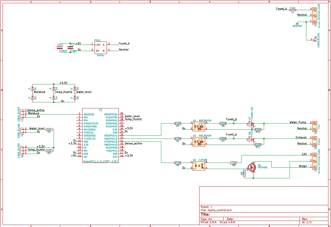
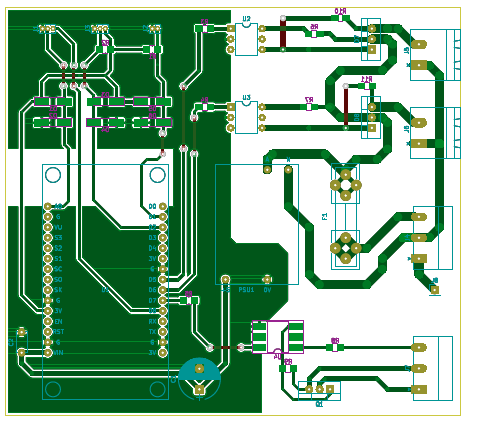
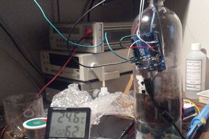
It will use an ESP8266 in the form of an NodeMCU 1.0 board ( I have some at hand) to provide processing power and WiFi connectivity.
240V devices will be switched using optocoupled Triacs with Zero crossing detection to minimize radiated noise.
12V solenoid driven by optocoupled MOSFET


 Darren Blaxcell, aka Pork
 J Gleyzes
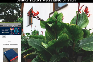
 Rahul Khanna
 M. Bindhammer
Hi, I was building this for my brother and he ended up moving so the whole project got shelved till he decides to re visit it again. So it never got finished