 Paul Andrews
For a while I have been putting together some reference hardware for a Nixies clock, and using it to test out some assumptions - basically, can I program it to do everything I want? So some basic requirements were:
- Can be re-programmed without dismantling it!
- Has a WiFi connection
- Can drive six Nixie tubes
- Can drive tube backlights
- Has a light sensor.
- Can dim the Nixies.
- Can turn off the HV side of the circuit
- Can be driven from USB and optionally LiPo
- Can take up to three button inputs.
- Can include an accelerometer.
What you see below is basically that.
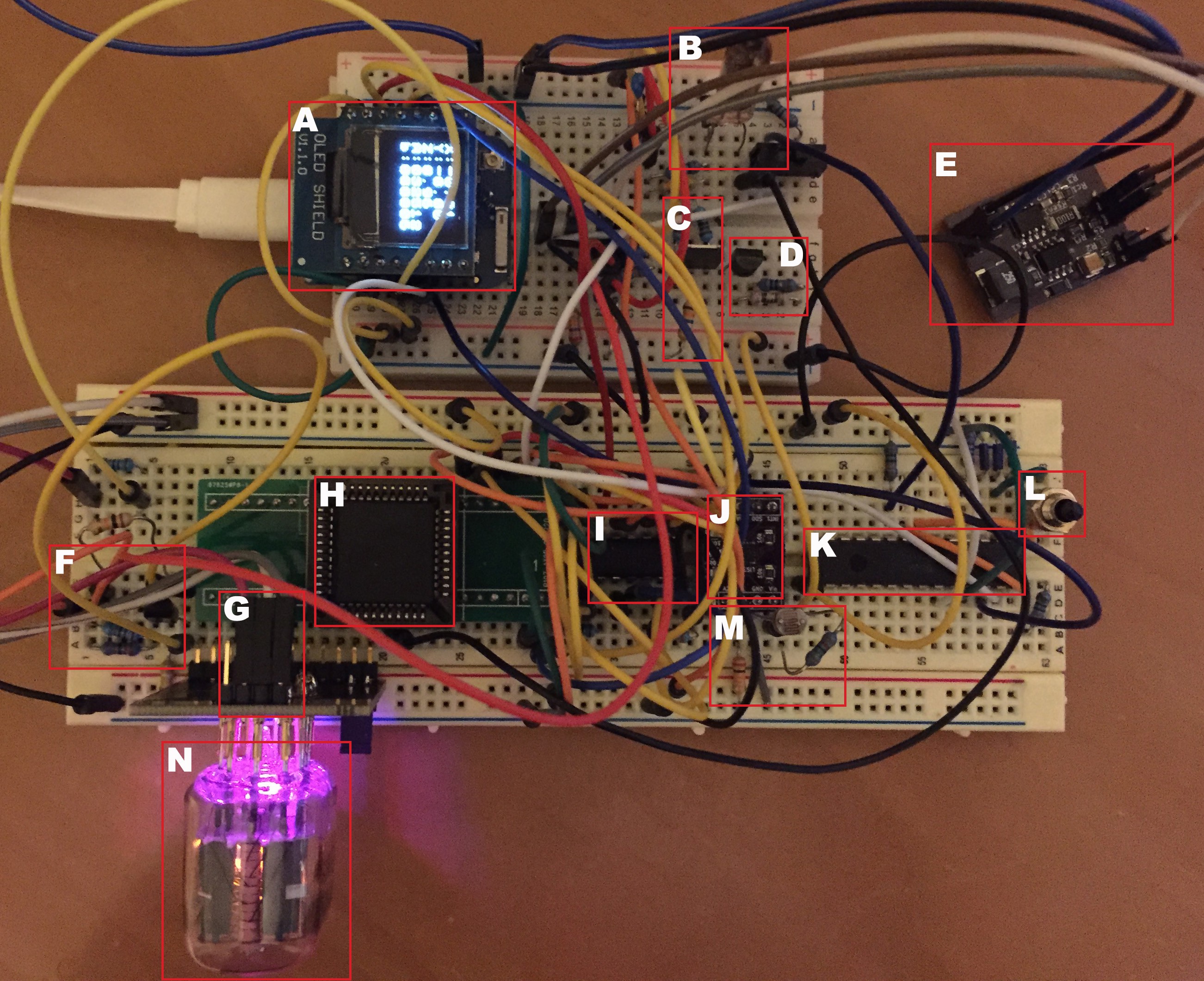
A. Is a Wemos D1 mini pro. It is basically an ESP8266 with all of the GPIOs broken out and it has a USB input. So this satisfies requirements 1, 2 and 8 in one go. What you can actually see is an OLED shield on which I am displaying some debug information.
B. Is a test colon-separator, an IN-3. I needed to develop the circuitry to drive it.
C, D and F are different implementations of a constant current source. I could use one of these instead of a current-limiting resistor.
E. Is one of my HV power supplies that I documented in another project log here on hackaday.io.
G. Is a connection to a NeoPixel on my adapter board. By using neopixels rather than RGB LEDs, I only have to dedicate one GPIO pin, and I can make each of them do something different if I want.
H. Is an HV9808. This is a high voltage shift register. It has 32 outputs, so it can drive three nixies plus change. It uses four GPIOs and is easily controlled using the SPI library. This particular chip uses 5V control levels and they can be daisy-chained together so I can control as many nixies as I like, with just the four GPIO pins.
I. Is a level shifter. The ESP8266 is a 3.3V chip, the HV9808 is a 5V chip. Sigh.
J. Is an accelerometer. It has an I2C interface, so it takes two GPIO pins, which it shares with any other I2C chips. It also happens to have an analog input, so I connected a light sensitive resistor to it.
K. Is an IO expander - it adds a bunch more digital out and analog in ports. Is also uses an I2C interface.
L. Is a test button connected to the IO expander.
M. Is the light sensitive resistor.
N. Is an actual nixie tube (an IN-12B) plugged in to one of my adapter boards.
The aim here was to test that everything I though I might need could actually be made to play nicely together. So far it does. My clock code does dimming, cross fading, HSV LED cycling, network time synchronization, reads the accelerometer, displays debug on the OLED, reads the button, controls an LED on the IO expander, presents a web page and I can program it over the air.
One thing noticeable by its absence is an RTC chip. With network time synchronization that automatically adjusts for timezone and DST, why would I need one? The ESP8266 clock is enough to keep time in between synchronizations. Still, I should probably add one just for completeness.
Here are some videos of it in action. The first is a little blurry, but it shows off the backlighting too. The nixie is a GR10J numicator (swoon):
This one is of CD-12 and shows the clock display a little better:
Anyway, we won't need all of this in my one-tube clock, and we'll change up some of the components while we're at it.
Discussions
Become a Hackaday.io Member
Create an account to leave a comment. Already have an account? Log In.