 Paul Andrews
Some Thoughts on the Next Version
Its great as it is, but here are what I would put in the next version:
A LiPo battery
I want to be able to carry this thing around from one place to another. It would be optional and just plugin in underneath the main board. I would need to add a boost converter from 3.7V - I need 5V for some of the logic. The power supply itself could run straight from the 3.7V. It would need to charge when plugged into a USB port.
So I guess I won't be dismantling my testbed just yet.
Fifteen HV Pins
I pull 12 HV pins out currently (plus another two for the little neon indicators). This is so I can drive tubes that have one or two decimal points. However there is a tube called the B7971 that is a 15 segment neon display. It is big. I can't drive it using this clock :-(. On the current connector I have one unused pin, so I would just need to add another two. In other words, instead of a 2x8, I would use a 2x9. That is a small change.
Real Time Clock
Currently it just syncs with the internet. But if I want to use it somewhere were I can't connect it to the internet, like my office, I need some other way of keeping the time. Actually I could add this now via the I2C expansion header, so maybe I don't need to add special support after all.
A Button
If I don't have access to the internet, I need some way of setting the time. Again, I could add this via the I2C expansion header. So maybe, I need to design a little add-on module for use away from the internet.
Hardware Notes
There are some not-so-obvious but important points about the PCB layout:
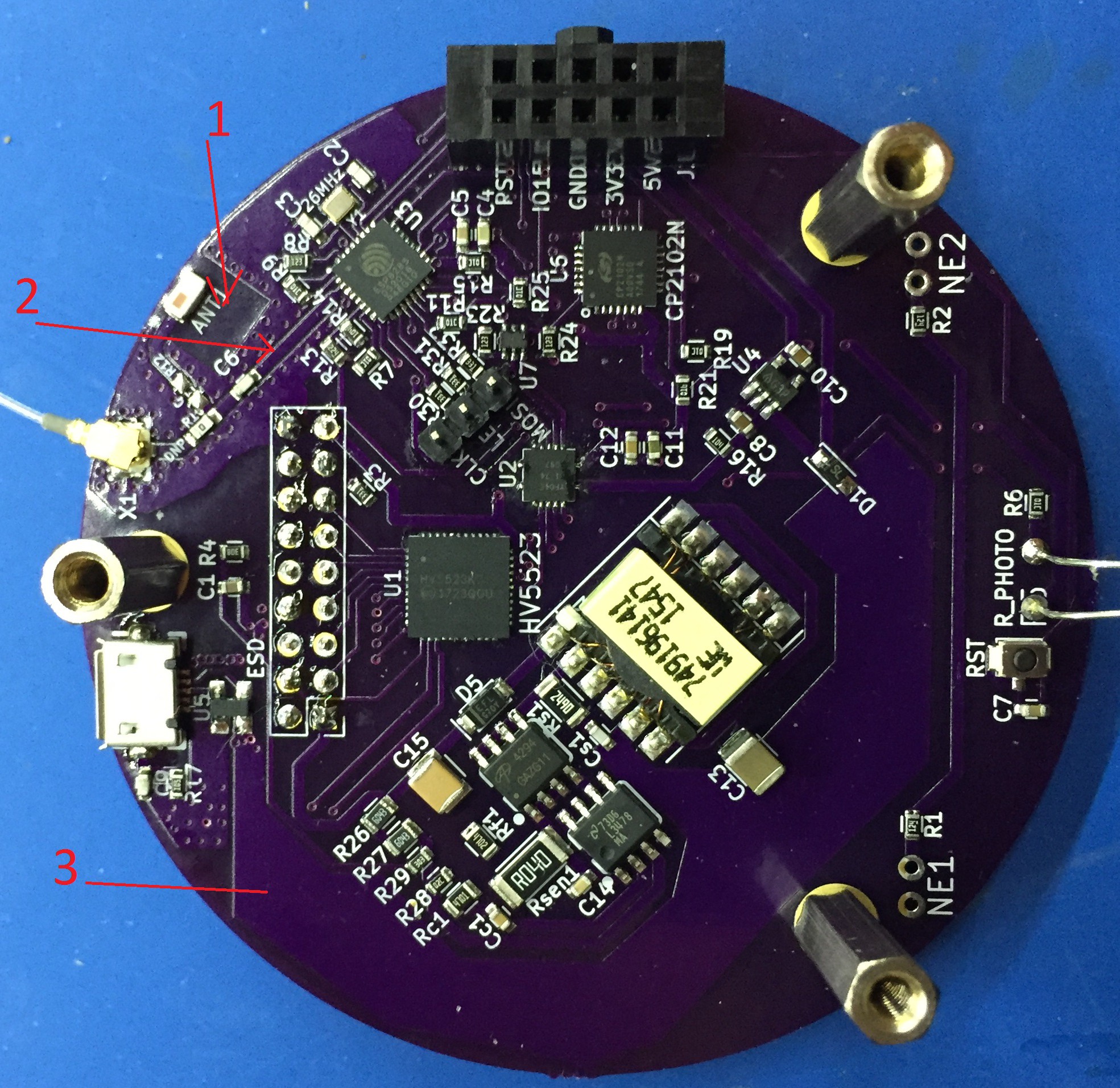
- The layout of the copper layer here (on both sides of the board) is defined by the manufacturer of the specific chip antenna.
- This is a 50 Ohm trace that leads from the ESP8285 to the antenna. The width is chosen specifically to match the copper depth and the characteristics of the substrate. KiCAD has tools that help to calculate this width given this information. OSHPark has the information needed to make this calculation. If you use a different fabricator, or a different spec board from OSHPark, you should re-do this trace. Though I am not sure how important it really is. On the flip side of this trace is an unbroken ground plane. No other traces can cross this trace underneath it.
- This +5V plane is kept as wide as possible to minimize resistance and hence minimize voltage drop when we start to pull more power.
You'll note that there are also many through-vias around the antenna traces with ground planes both top and bottom. This is to minimize stray EM radiation.
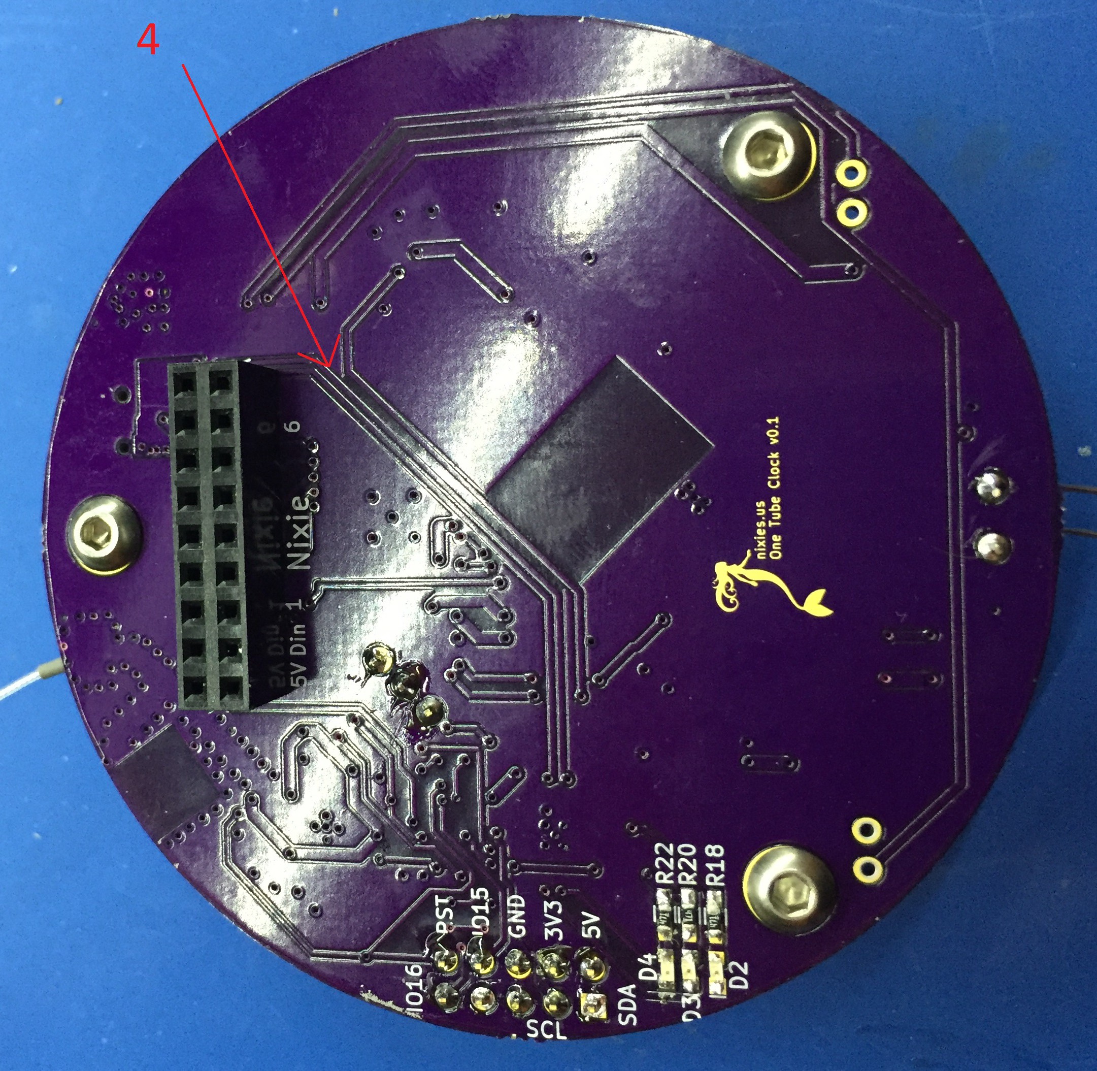
This pair of traces are the USB data lines. They should really be a differential pair. Like the antenna trace, the impedance is important, but here layout is also important. I kept them parallel, but that was about it. The CP2102N is a full speed device. We shouldn't really need to worry until the traces get up to about six inches in length.
Software Notes
I'm pushing it with the ESPxxxx devices. I was careful to test out my code before I committed to using them. The problem is that the WiFi gets priority over everything else, so anything that is sensitive to timing can get thrown out. This is particularly important for the NeoPixels, which use a clockless protocol. In fact at one point I updated my ESP8266 Arduino libraries to v2.4.0, and the NeoPixels started glitching on me. Down-graded back to v2.3.0, and all is well - there is still a chance they will glitch, but I haven't noticed it in all the months I have been using it.
Allegedly the ESP32 would be better in this regard - it has a separate core for the networking.
Discussions
Become a Hackaday.io Member
Create an account to leave a comment. Already have an account? Log In.