 ZeptoBit
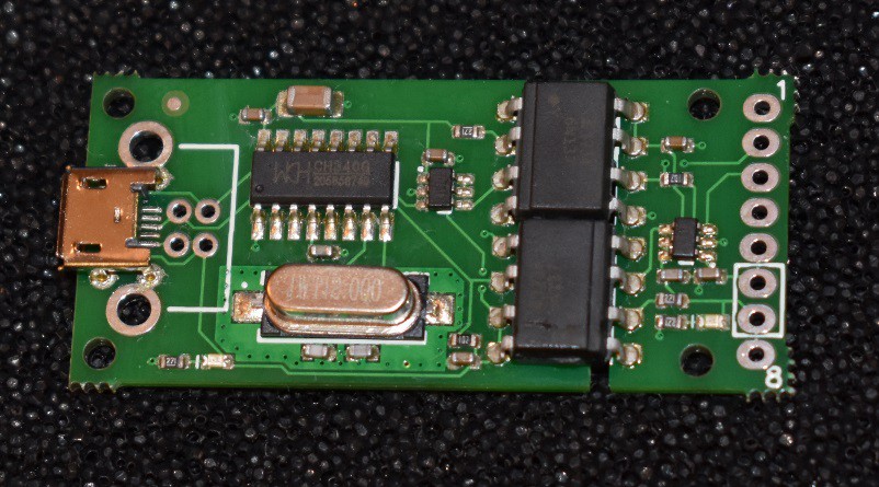
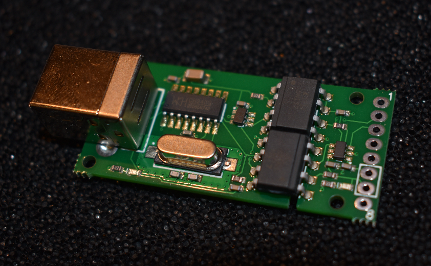
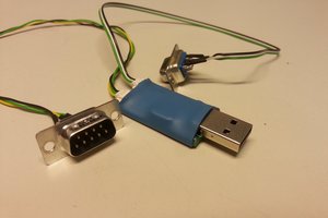
I designed this adapter because I wanted to use it with other projects I was working on. Appart from it's main feature, optical insualtion, it has two features missing in many other USB-UART adapters:
It works with signal levels from 1.8V to 5V, while many adapters only works at 3.3V to 5V.
Secondly I wanted the driver to be as trouble free as possible. The CH340 USB chip provides this, it "just works" with no driver installation on recent Windows and Linux versions.
Main Features:
- Supports all common baud rates from 300 baud to 2 Mbaud.
- Works with IO levels from 1.8V to 5V.
- No driver installation required on Windows 10 or on recent Linux versions.
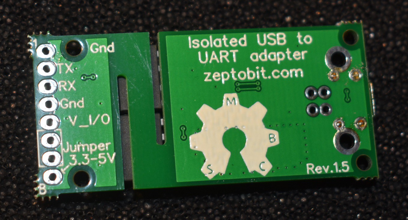
- Avoids ground loops.
- Circuits ground and computer ground does not need to be at the same potential.
- Maintains isolation from mains supply.
- Protects the computers USB port from damage.
- Separates sensitive analog circuits from potentially noisy computer ground.
- Works with devices which can not drive an opto isolator directly.
- Open source hardware: All the documentation needed to repair or modify the adapter is provided including schematic, BOM and design notes. 3D models of the device and 3D printable enclosures are also available.
Available on Kickstarter
The adapter can be pre-ordered on Kickstarter.
Downloads
Coming soon: Schematic in DipTrace .dch format
Coming soon: 3D model of the board and 3D printable enclosures
Open Source Hardware
The ZeptoBit Optically Isolated USB-UART adapter is open source hardware, licensed under Creative Commons – Attribution 3.0.
The following is released as open source:
- Schematic in Diptrace and .pdf format.
- Bill of Materials
- Design Notes (principles of operation)
- Mechanical CAD files for adapter and enclosures. (Not ready yet, will be released before the end of the Kickstarter campaign.)
The following is not released as open source:
- Board layout files, Gerber/drill files
Since I'm not releasing the board layout files/gerbers I don't think it would be appropriate to use the OSHW gear logo. Instead I'm using a modified version with letters to show which parts are open source, as proposed by David Jones. I think this is a good solution as it shows at a glance which parts are open source and which are not. The logo on the board is missing the "D", that will be fixed in the next batch.

 Łukasz Przeniosło
 Colin O'Flynn
 Sven Gregori
 Adam Feuer
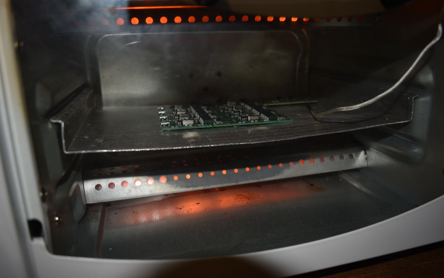
this kind of reflow solder is not reliable sometime. have a try of Makerfabs prototype/small batch PCBA production.