As described in its datasheet, the MCP73831 LiPo battery charger is designed to detect the presence of a battery by sourcing 6 μA of current and detecting the voltage. If a battery is present, the voltage should stay below about 4.3 V. If the battery is not present, there should be a large impedance so the voltage rises past 4.3 V. Unfortunately, the first revision had the load (the LDO supplying VCC) in parallel, so to the battery charger it seemed that there was always a battery connected.
Charging LiPos typically works in two stages: an initial constant current stage until the voltage reaches nominal battery voltage and then a constant voltage mode is entered. The MCP73831 also has a third preconditioning stage that happens before the constant current stage if the voltage is very low; this supplies a smaller constant current. I believe that having the load in parallel with the battery should still work as long as the load draws less current than provided in constant current mode. This would just mean that part of the current would be diverted from the battery but it would still at some point enter constant voltage.
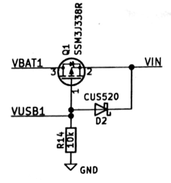
Nevertheless, I wanted to correct this in the second revision. My solution was to switch the LDO's supply to 5 V from USB once a USB cable is inserted. This is done with Q1 shown below. When USB is disconnected, the gate of the PFET is low so VIN is connected to VBAT1. I chose a PFET that has a low on-resistance. When the USB cable is inserted, the PFET turns off and VIN is supplied from VUSB1 through the Schottky diode (which has a forward voltage less than a regular diode).
I the second revision, I also wanted to try out a "stacked" approach, with two PCBs mounted on top of each other. I did this by laying out two PCBs with matching dimensions and header connector. They were connected with mouse bites so I did not need to pay for fabricating two PCB designs. I also added a programming portion connected with mouse bites that can be snapped off after programming.
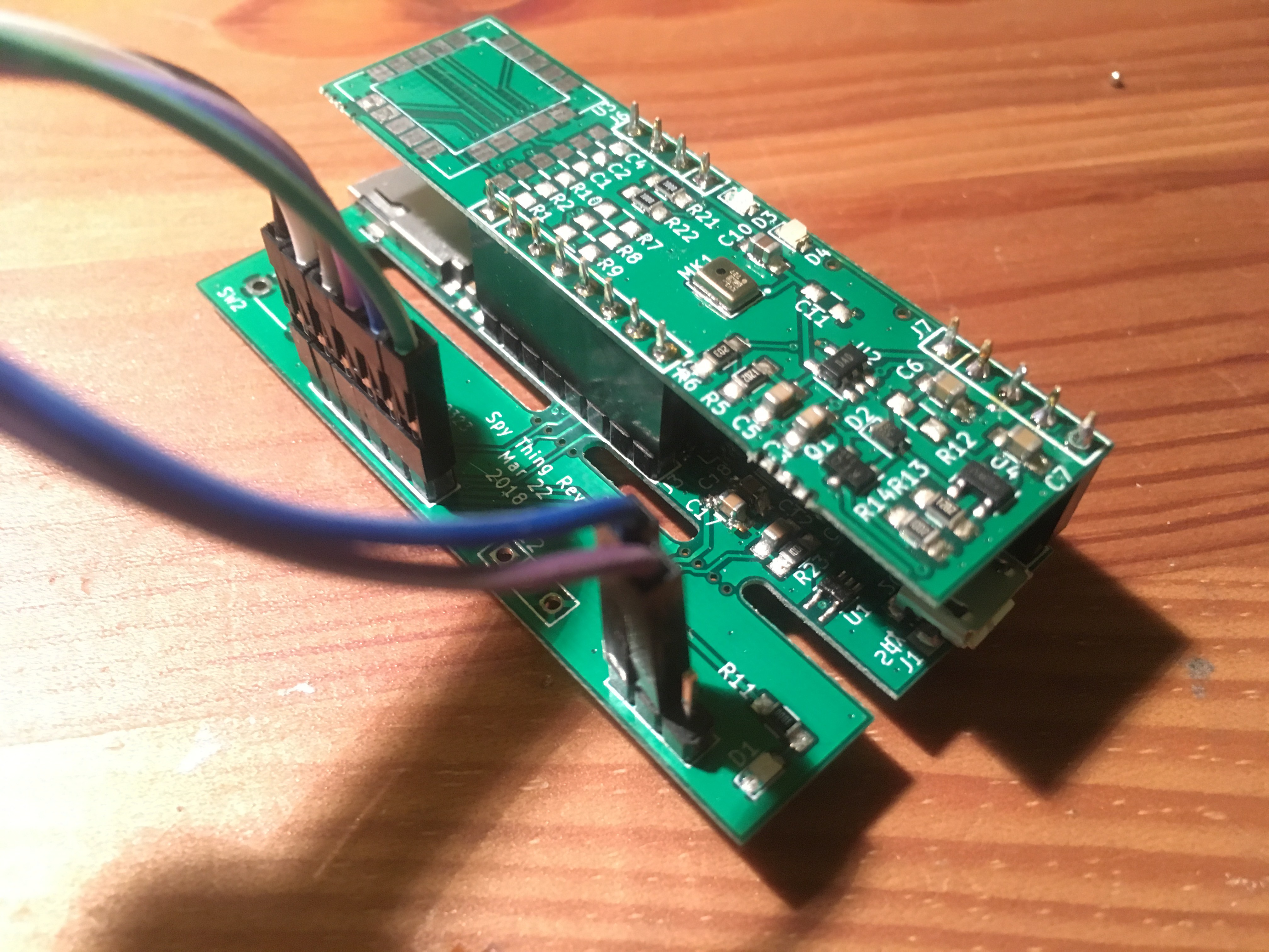
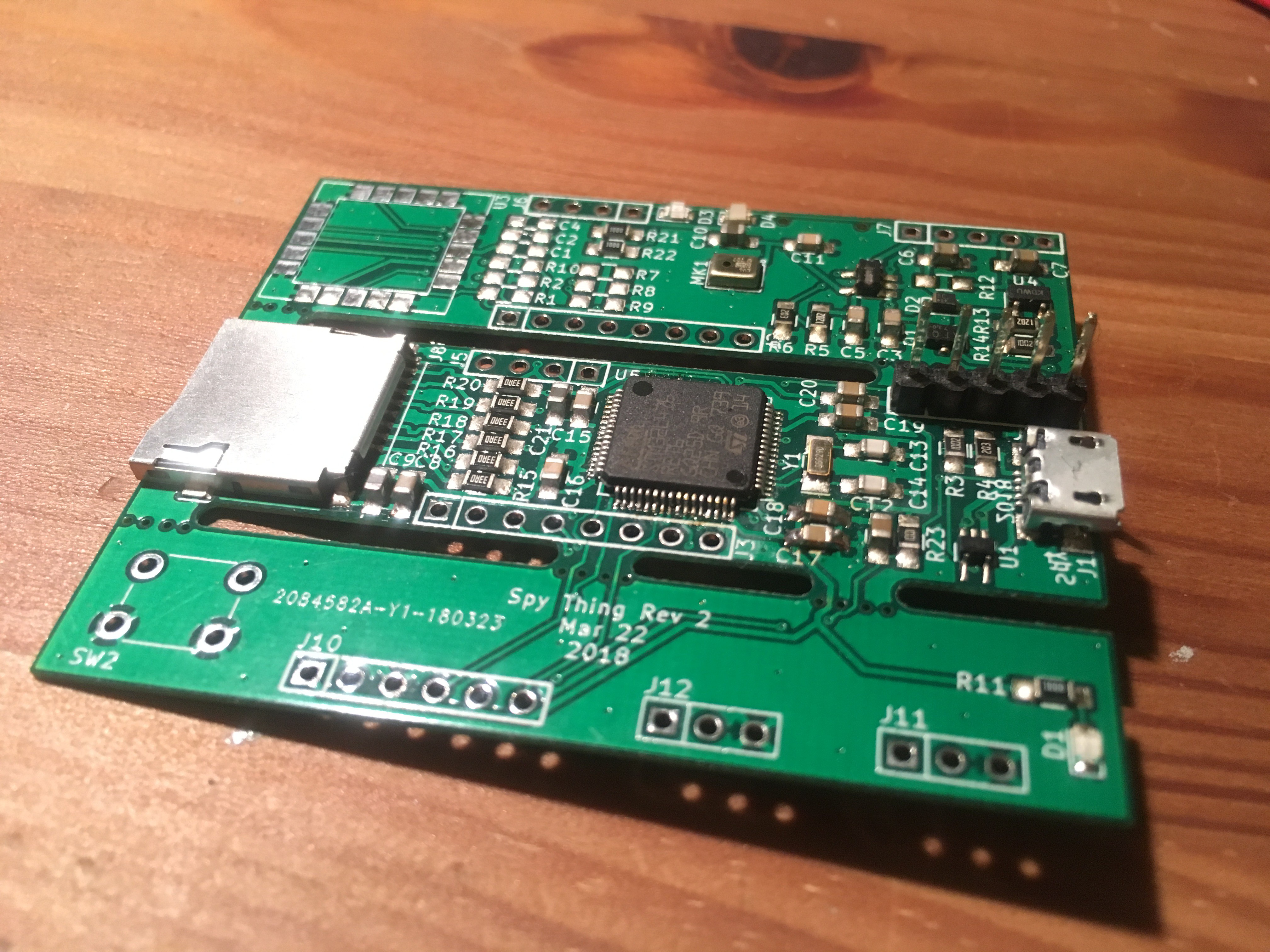
I tried connected it up and it seemed fine before I snapped it apart. However, after snapping it apart and connecting it together, it seemed that the ground on one of the headers was not connected! KiCAD had told me that there were no unconnected nets. However, it turned out that one of the "connections" was through the ground plane through the mouse bites connected the three parts together.
Onto revision 3! In revision 2 I ditched the RFM95W and battery gauge but I plan to add these back in revision 3. I think I'll also go back to a single 4-layer board, but with components on both sides so I can make it more compact.
Discussions
Become a Hackaday.io Member
Create an account to leave a comment. Already have an account? Log In.