 Bruce Land
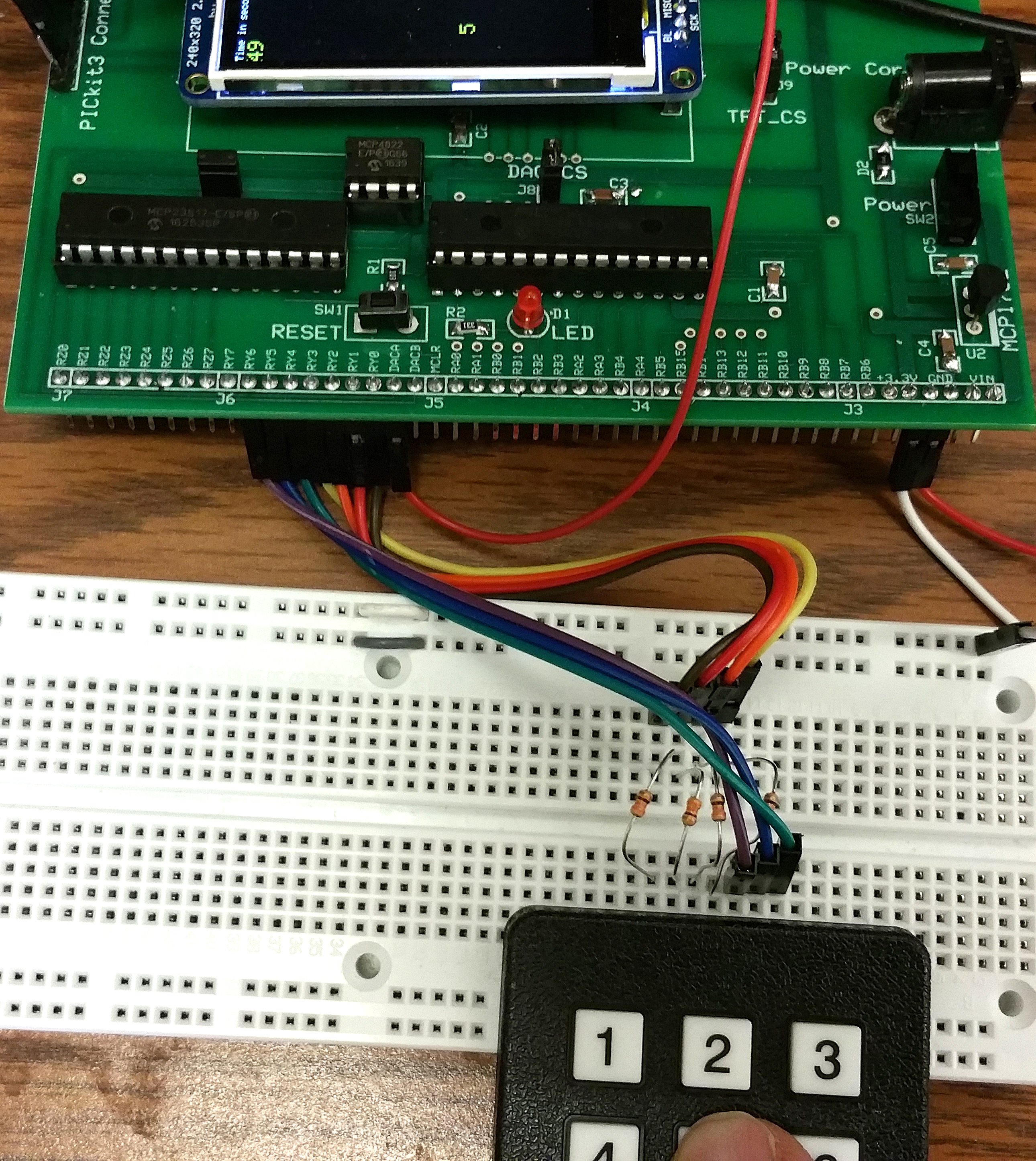
Keypad using Port Expander example uses a new environment which includes the port expander library (details below). Download the ZIP and the source code which implements the keypad scanner using the port expander on the big board pinout shown on the left below. Included in the ZIP file is the portexpander.h and portexpander.c corrected and extended for the big board. This example adds to Sean's version by allowing the DAC and port expander to share an SPI channel without conflict (except timing). The port expander docs name the two 8-bit ports A and B, but to avoid confusion with the PIC ports of the same name, Sean refers to the expander ports as Y and Z on the big board and in the interface library. The keypad is connected to port pins Y0 to Y6. Y0 to Y3 are driven as outputs, while Y4, Y5 and Y6 are inputs with pullups turned on (there are no pulldowns on the expander). The scanner logic has to be modifed for active-low outputs, but the scanner output is the same as before. The scanner returns 0 to 11 for a valid key, and -1 if there is no valid keypress. Since the DAC is driven from an ISR (and is on the same SPI channel), and since the keypad takes several SPI interactions to complete a write-read cycle, it is necessary to define a critical section in the code to disable the ISR for a few microeconds while write/reading the port expander SPI channel. Two of the port expander's Z port pins are used to test bitwise i/o functions.
--
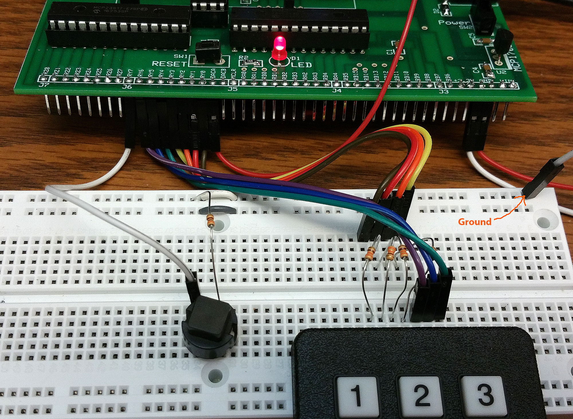
The image on the right includes an extra switch which acts as a shift-key for the keypad and which is connected to Y7 (with pullup turned on). The source code supports 24 unique button codes and displays them on the TFT for testing using the printline function. The switch is connected through a 300 ohm resistor to ground, when pushed, and is pulled-up internally. If you float the input, the code behaves in the same way as the keypad with no shift key attached.
Port Expander Details. Sean Carroll wrote support code for a port expander which gives the PIC32 16 more i/o lines, running at SPI rate of around a transaction per microsecond. Sean Carroll structured the code to look as much like the PLIB commands for ports A/B as possible. There are two ports named Y and Z, each with 8 bits of bidirectional general i/o.The example above that reads the keypad using the big board and displays the result on the TFT-LCD uses a slightly modified portexpander.c file from Sean's version to accomodate board connections and simultaneous use of the DAC, which shares an SPI channel. The port expander max SPI clock speed is 10 MHz, so the DAC is running slower also. (This is Sean's version with examples of using interrupts, but do not use the pin layout with the big board. Using the Port Expander and ZIP code (Sean Carroll))
More details at
http://people.ece.cornell.edu/land/courses/ece4760/PIC32/target_board.html
 doctek
 Fabio
Fabio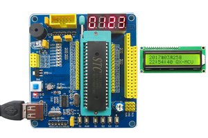
 Ken Yap
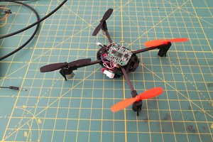
 lb5tr
lb5tr