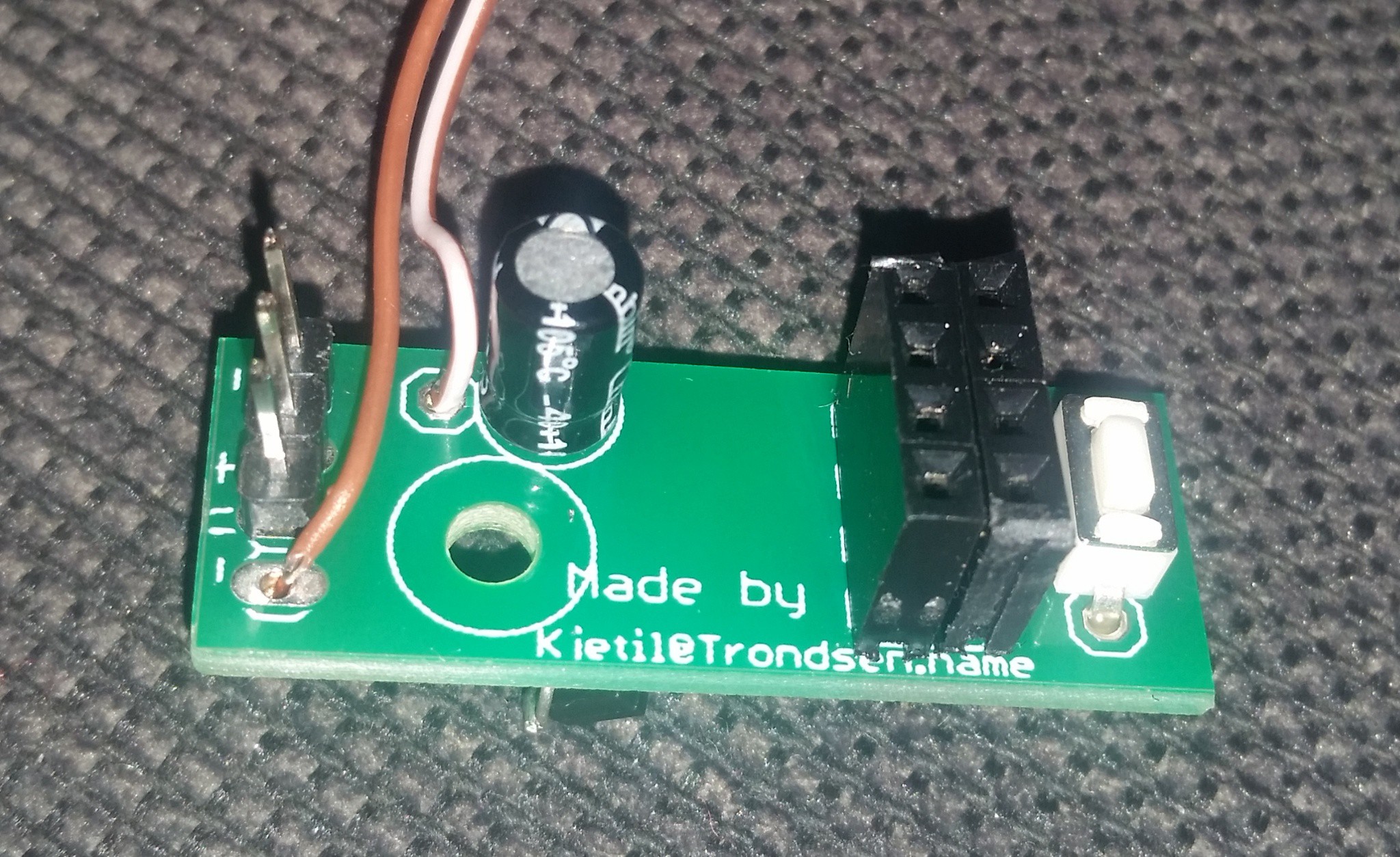
Today I got the PCBs I did design.
Here is the bottom side. The unused pads to the right is for the clock-project. The unused to the left is for a extra filtering capacitor if needed.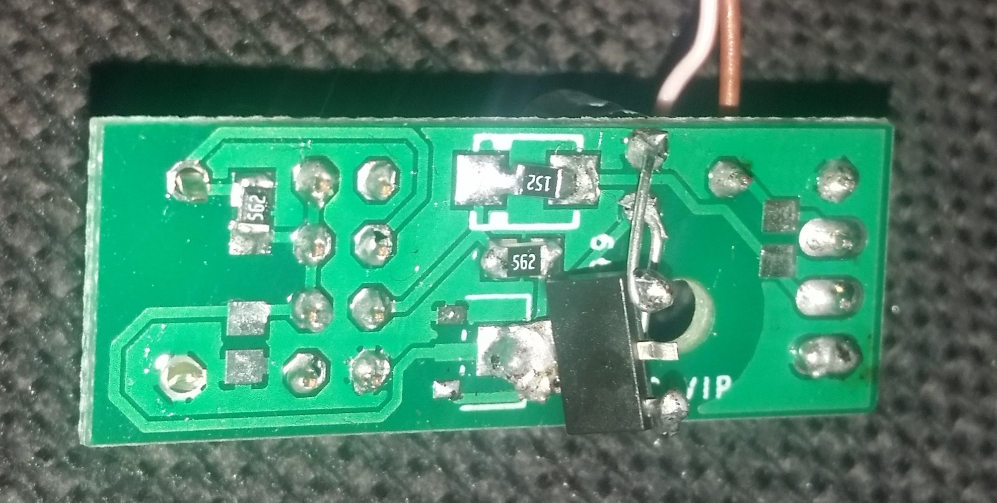
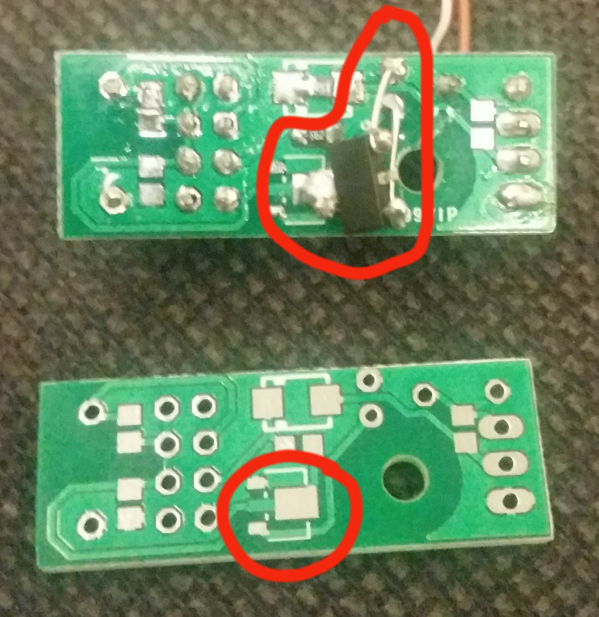
I found 2 errors in the design. the footprint for the resistor in the top center is a litle to big. It is marked as an diode because in the clock project it will be an diode. It was not a problem, but I will fix it in the design file. The other error was worse. I used wrong footprint for the voltage regulator. Not only that. But at the same time I used the pinout of the regulator i had, so there is no regulator fitting in the footprint with the pinout I used. The fix is marked in the image with red. Out on the regulator is soldered to the PCB, while the leads from the capacitor is soldered to gnd and in on the regulator.
Here the PCB is put in place in the enclosure. The screw used for mounting the PCB is the leftover from the servo. It comes with 2 screws, the other is used to fasten the needle. I fill the mounting hole for the servo with some hot glue before press fitting the servo.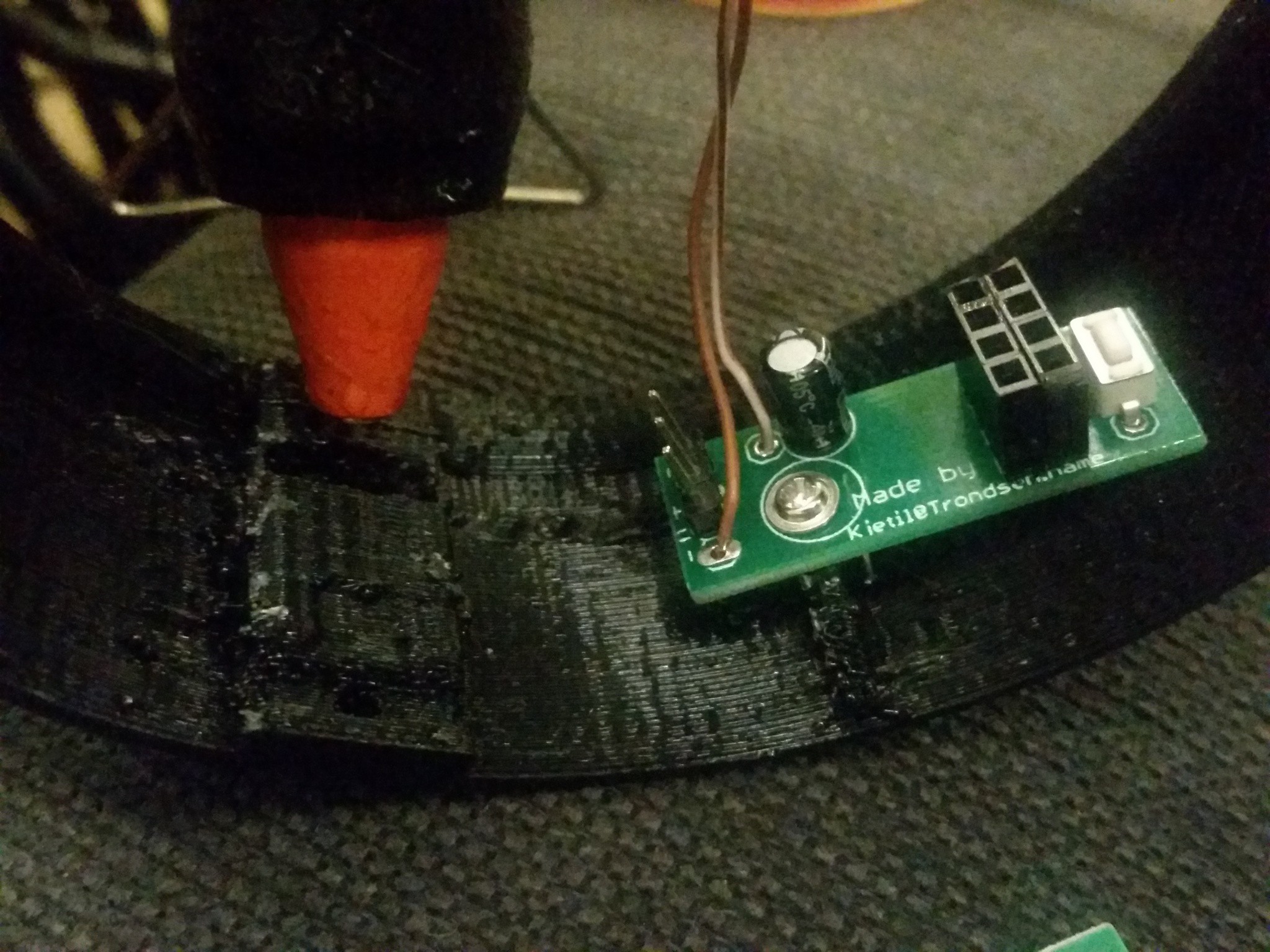
After adding the ESP module and a cable tie to cleanup the inside looks like this.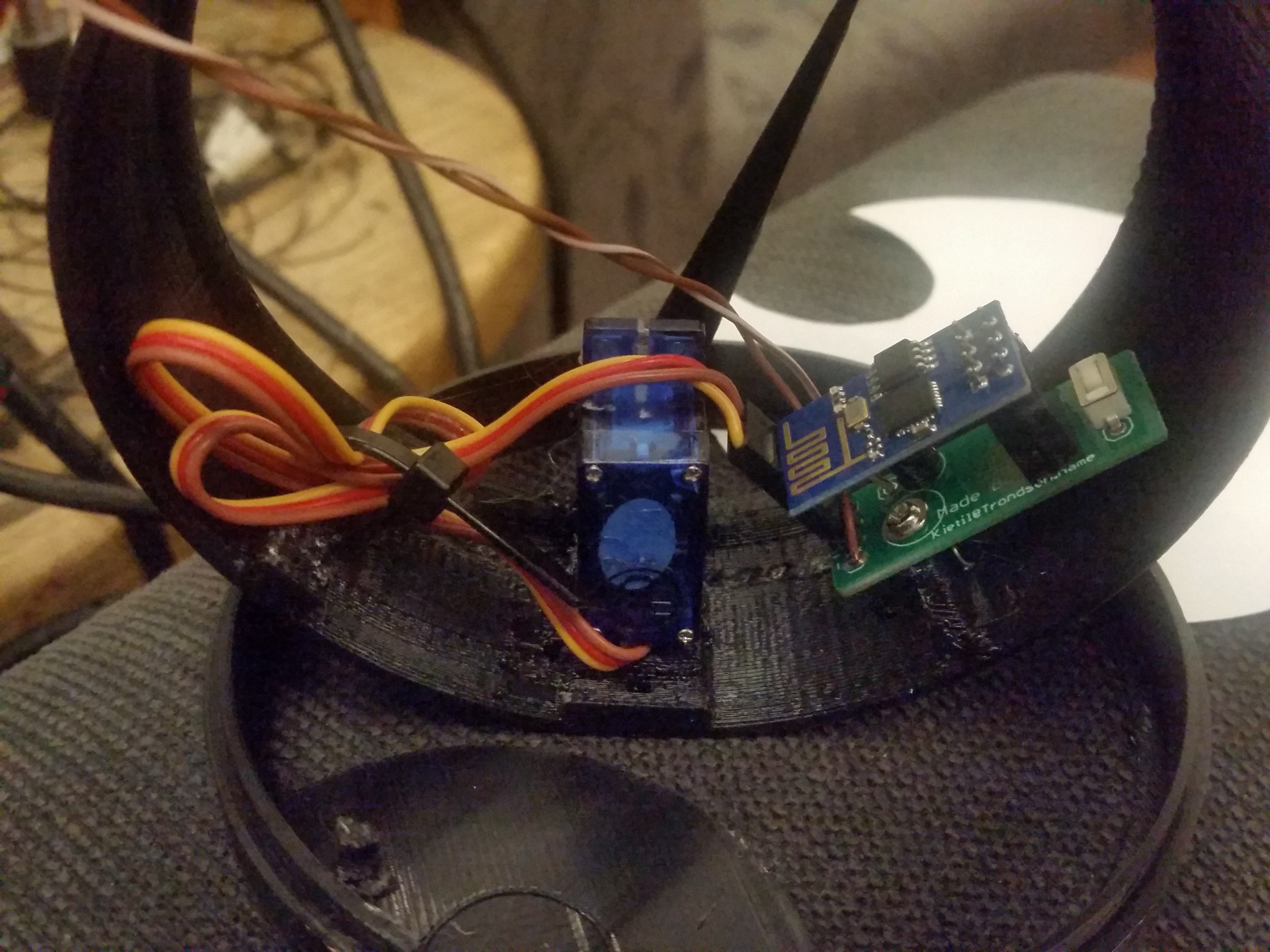
Normally you would have the power cable enter through the hole in the bottom and secure it on the inside, but in this particular case I just grab some power from the neighbor unit.
And here they are. on the side of a bookshelf giving instant status of our servers.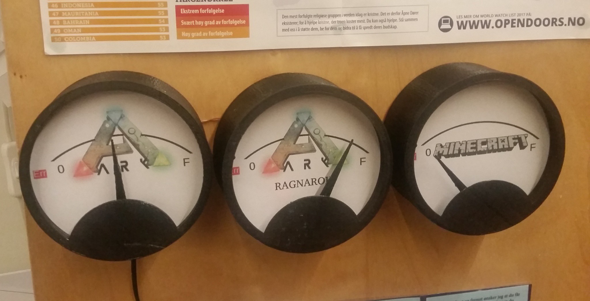
I have also found an other error. The software needs to be a little more tolerant before marking Err on steam servers. I will update the software. but not today. New software and new design files for the PCB will be published sometime in next week.
Discussions
Become a Hackaday.io Member
Create an account to leave a comment. Already have an account? Log In.