 shlonkin
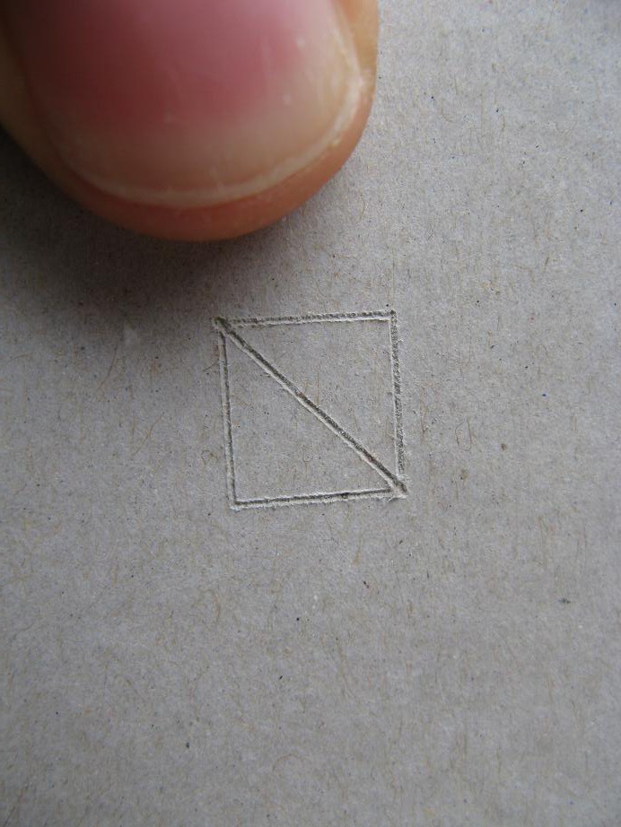
Before you get too excited, that first cut was just in dense cardboard, not the real thing. But we'll get to that shortly.
As I mentioned before, I really needed a new z-axis design, so I went to the place where I can really concentrate and piece things together in my mind, the hardware store. I eventually decided on the following:
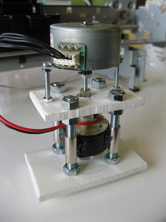 I think the picture is pretty self explanatory, but I'll try to describe it. Note that everything is temporarily tacked together with hot glue. The idea is that the final device will be held together with a much more permanent and strong adhesive, but you know, sometimes I get lazy and the hot glue stays if it works. The top motor is a 7.5degree/step, 4-winding, unipolar stepper that I probably got from a fax machine. It is coupled via a 3mm screw and long nut to the cutting motor. Both of these run on 12V.
The bottom motor is snugly fixed between four bushings that ride up and down 6mm bolts. I was really careful with positioning, so there is almost no lateral play in the motor, and the bushings slide with ease.
The white structure is made from a cutting board pulled out of the garbage. I love working with that stuff. If you ever find such a chunk of plastic, don't pass it up.
The stepper is driven with a convenient darlington array with built in clamping diodes. I don't remember what I pulled that out of, but it was a lucky find. Here is the updated controller (I'll post schematics once they are finalized):
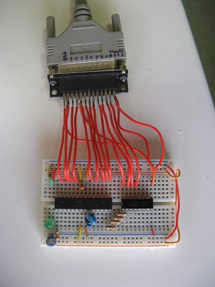 Notice that I have now switched to a stand alone microcontroller, but it still makes use of Arduino. The smaller chip is the darlington array.
What is the cost of this new z-axis? The only things I had to buy were some of the screws, nuts and bushings. It came to 200 yen (about $2).
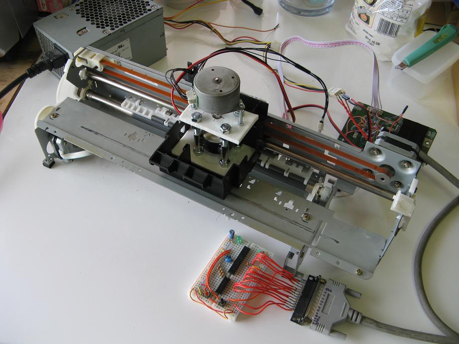
And here it is in place:
 And finally, the part you've all been waiting for. I just had to give it a test drive to see what happens, so I stuck some dense cardboard in it and cut a little 1cm square thing. Everything worked smoothly and the result looks great. Now if i can get a similar result on an actual pcb I will be filled with joy.
Discussions
Become a Hackaday.io Member
Create an account to leave a comment. Already have an account? Log In.
When do ya think you will post the controller schematics ?
Are you sure? yes | no
Are you sure? yes | no
Are you sure? yes | no