 Thomas
Before diving further into this project I first had to figure out how the moving heads work.
The CLMHRGB25W is surprisingly easy to take apart. Removing a few standard phillips bolts is all it takes to access the insides.
By taking apart the base I found the controller board:
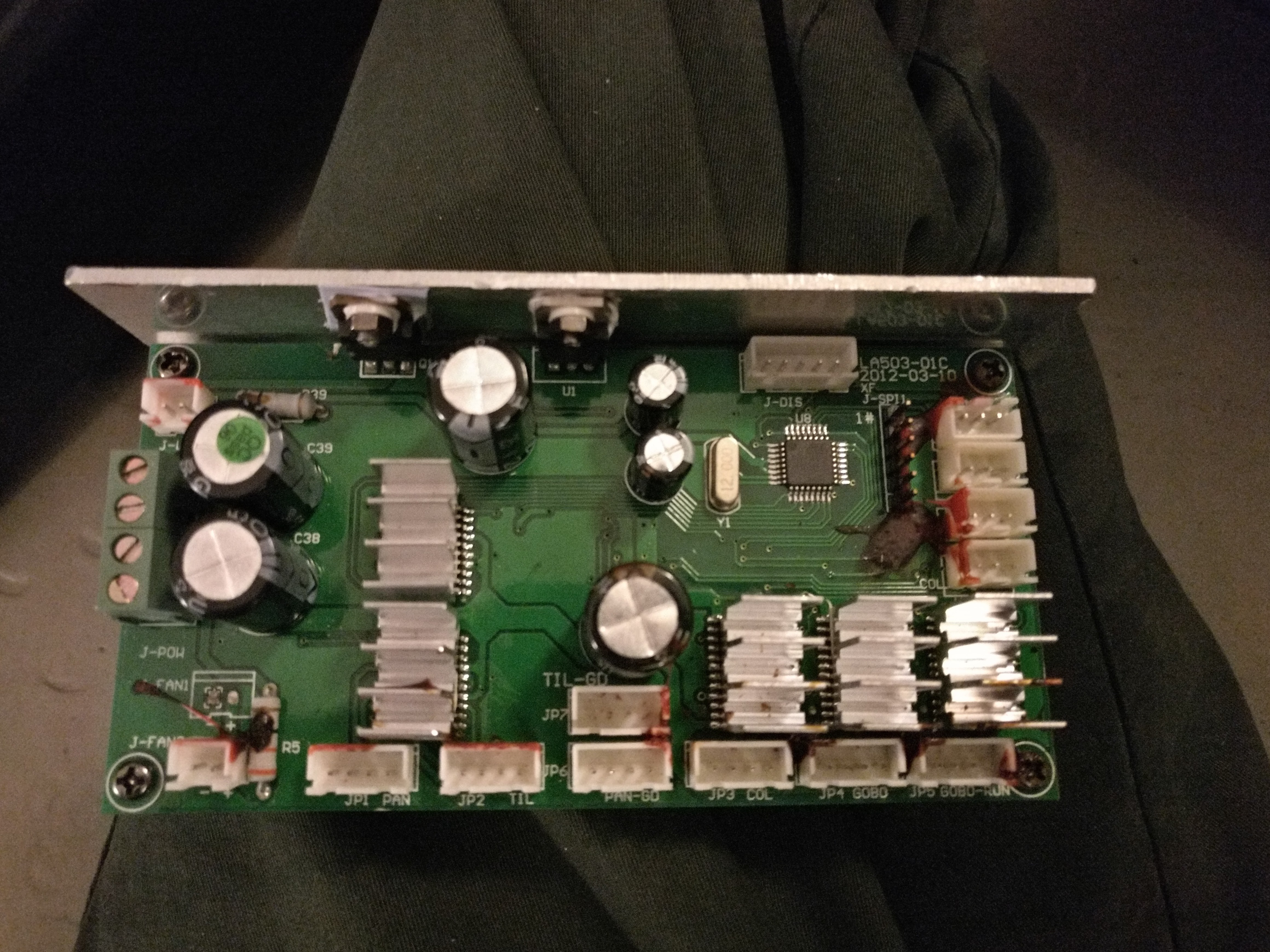 It is very similar to what you would find in a 3D printer. It features five stepper motor drivers, three endstop inputs, two encoder inputs, one DMX input, one 4-character 7-segment display output, two MOSFET outputs for powering the light source and fan and two power inputs. It's all controlled by a small 12MHz MCU. There's also one (unused) SPI header. The backside is scattered with tiny surface mount passives. Nothing too surprising here.
 If you're not familiar with moving heads you might be wondering why 5 stepper drivers are needed for just pan and tilt. Opening up the top reveals the answer:
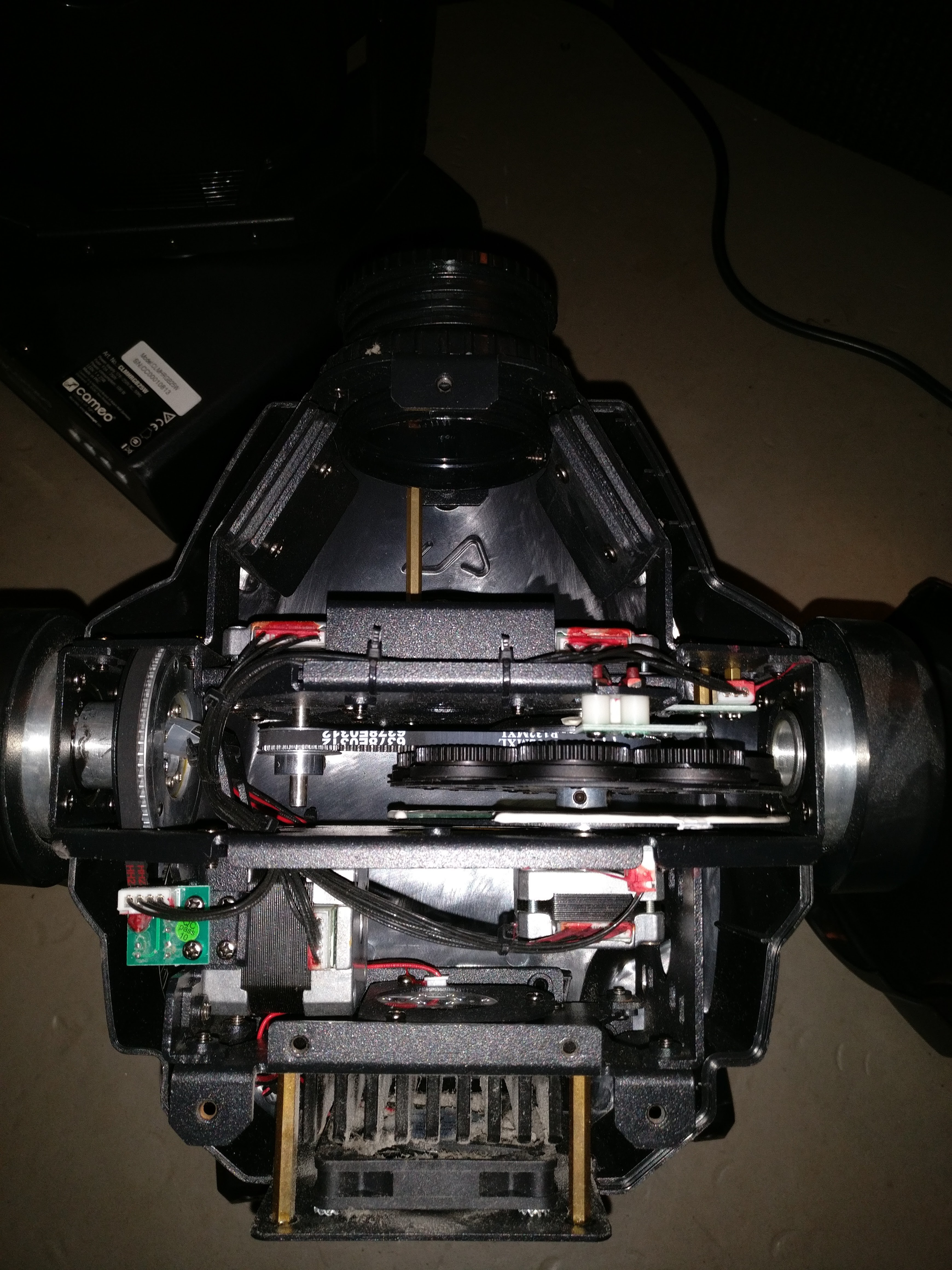
The remaining three steppers are used for selecting one of the 8 gobos, rotating the gobos and rotating the color wheel. All of these can be replaced by an LCD. This would convert the entire optical system to fully solid state and allow for an infinite number of colors and patterns and even projecting videos!
Each of these three axes use open loop control and uses a magnet + hall-effect sensor as endstops for homing.
The pan and tilt axes however have no endstops. Instead they use optical incremental encoders:
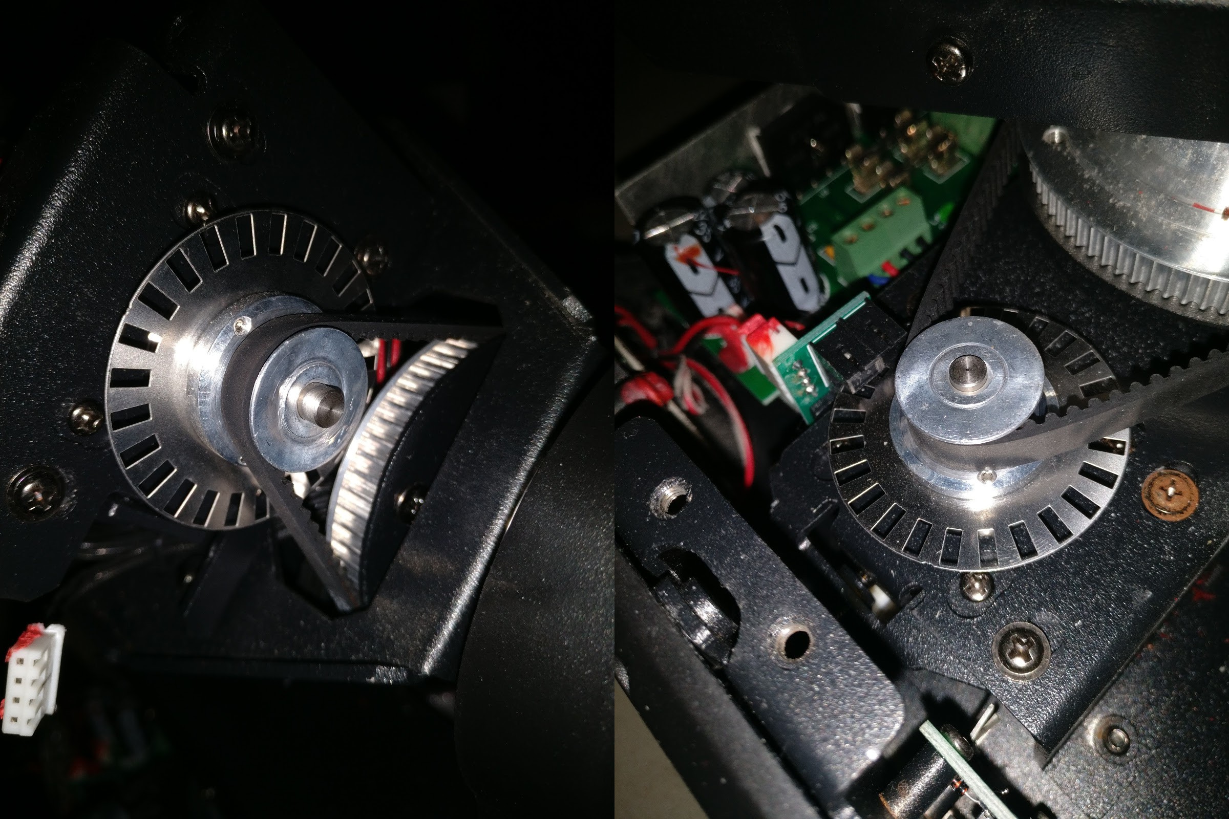
As far as I can tell the homing procedure for these axes consists of monitoring the encoders while each of the axes turn towards their limits and detect when the motor stalls.
Next up is the light source. Most of the moving heads would not light up so I was afraid that the light source was dead so I removed it so I could test it separately.
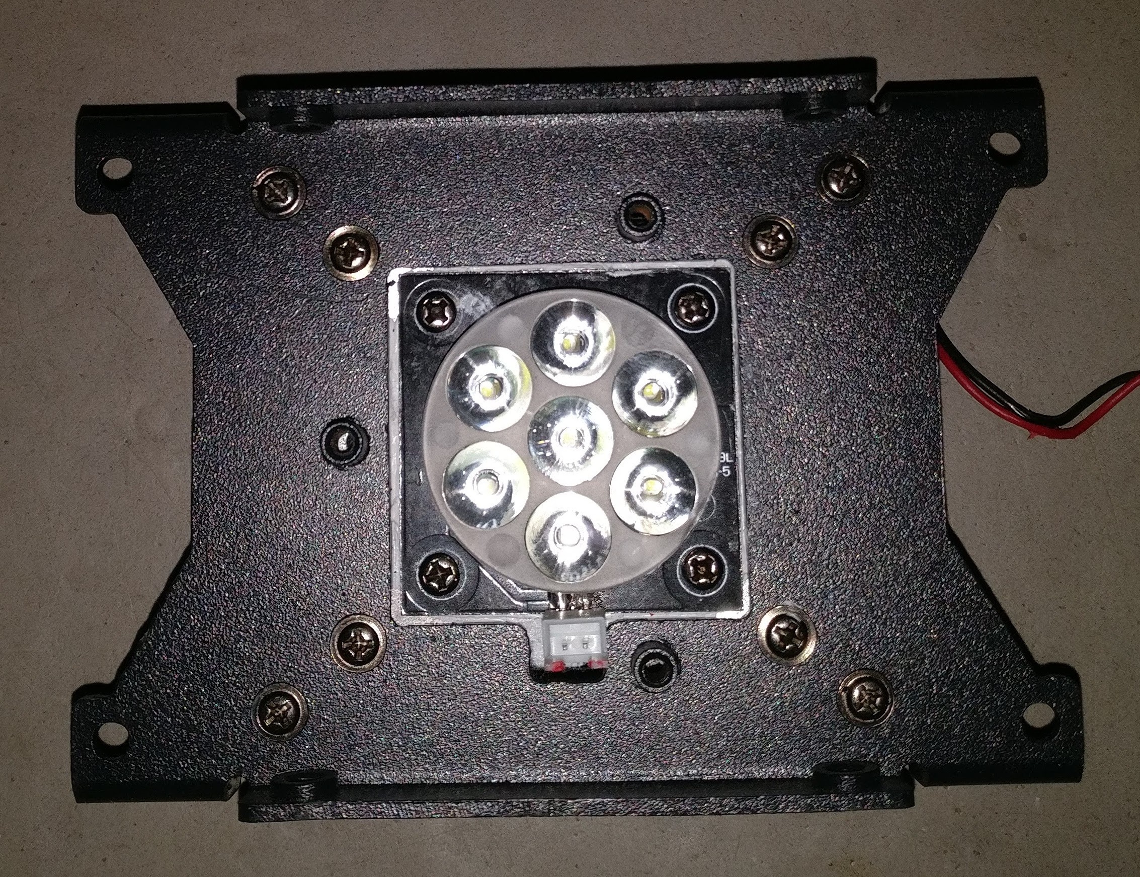
The light source consists of 7 bright white SMT LEDs connected in series and mounted on an aluminium PCB. On top is a small plastic lens assembly for focusing. The PCB is attached to a relatively large heatsink with some thermal paste. A fan is attached to the back of the heatsink for extra cooling. On the side of the heatsink we find an interesting component: A TO-220 style package with only two leads and "KSD-01F" written on it. A little bit of research reveals that it is a thermostat which cuts off all current to the LEDs if it reaches more than 60C. A simple way of preventing overheating. I tested the LEDs using a current limited adjustable benchtop power supply.
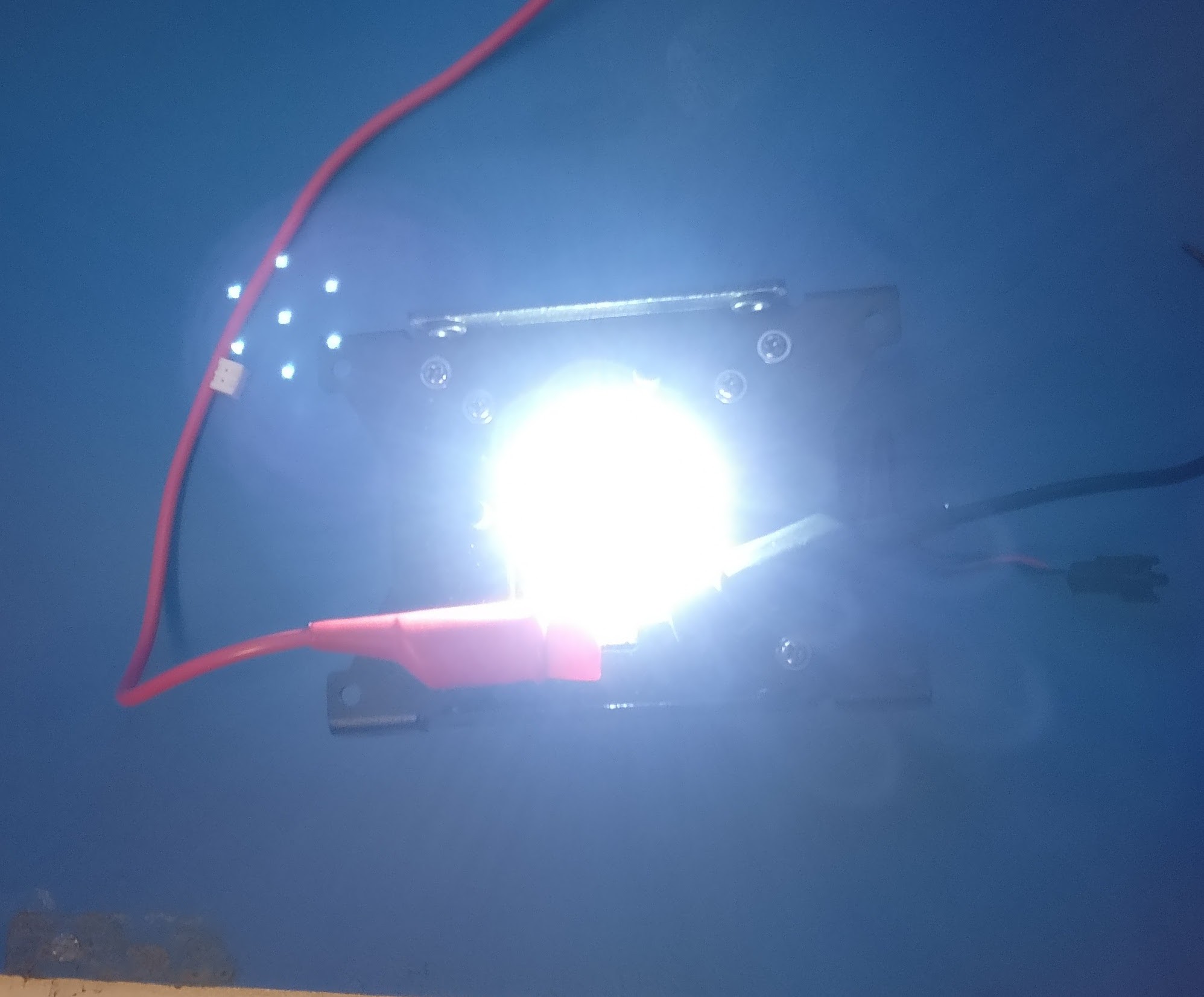
It definitely works! At 350mA the voltage drop across all 7 diodes is 20.65V, meaning that the forward voltage drop per diode is around 2.95V.
That's it for this log entry!
Discussions
Become a Hackaday.io Member
Create an account to leave a comment. Already have an account? Log In.