 Eric Hertz
As part of my house-battery charging system, I thought maybe to use a light-bulb, instead of a resistor, as the current-limiter.
Pretty simple, place lightbulb in series between voltage-source and battery.
The idea came to mind as I sat outside a physical electronics-parts store (they still exist!) contemplating worst-case scenarios and the supplies available. 80W, I determined, through something like 0.1ohms. None-a-dem resistors were *even close* to that wattage.
But, yahknow, lightbulbs are darn near a wire and capable of handling 100W. If powered normally, there must be *some* resistance, otherwise they wouldn't stop at 100W! But, last I recall measuring with a meter, probably 15+ years ago, the resistance was near zero. So there must be an I-V curve, their resistance must increase when powered... right?
And, that's exactly what I'd want; a higher resistance when my battery's really low, so my charging circuit won't blow my fuse, and a lower resistance when the battery is nearly charged, to cram in as many electrons as possible (again, without blowing the fuse).
Cool. And after finding I-V curves showing just what I'd guessed, I had it in mind to see if anyone's tried it... Sure enough. It was actually pretty common back in the day. And there's even a video of a dude charging a car battery from 240VAC, rectified, with nothing limiting the voltage/current other than a series lightbulb.
Not *quite* what I had in mind, but concept-proven.
I started thinking about it, though...
The I-V (V-I?) curves didn't show extreme cases, extrapolation was necessary for e.g. the resistance of a 100W 120V bulb running at 12V (nevermind the ~2V difference when the battery's nearly full). So, it comes down to buying a bulb and measuring.
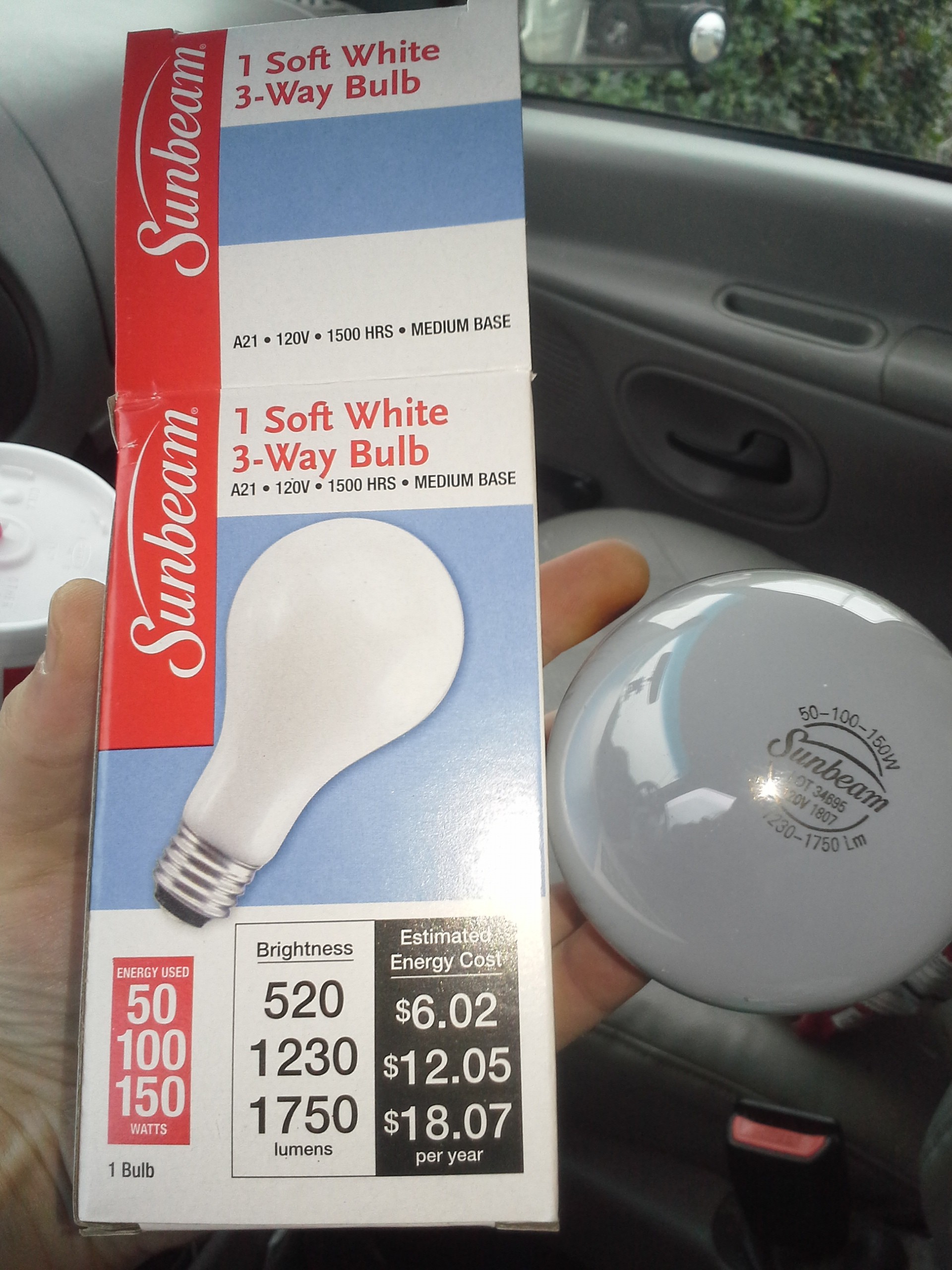
Figured this 3-way bulb would give me more options... (4!)
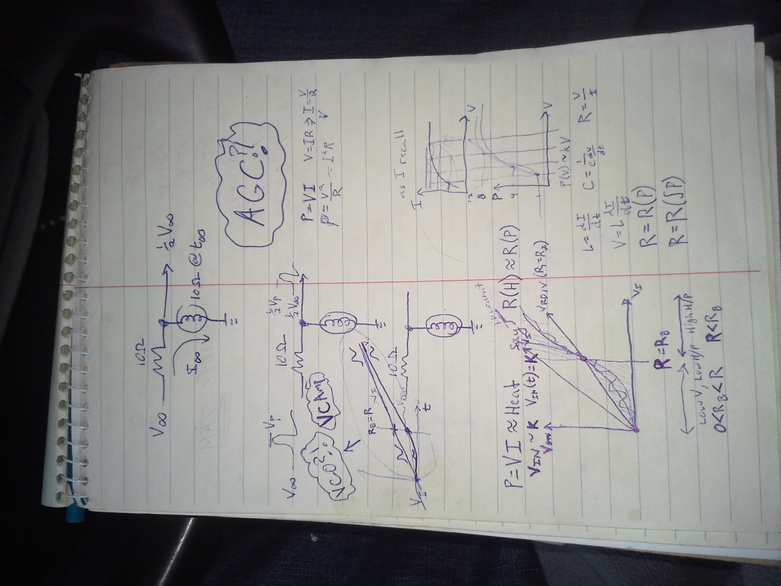
Measurements: ~10ohms and ~20ohms. Much too high for my needs. But, V=IR P=VI=V*V/R, R=V*V/P=120*120/100=14400/100=144 ohms vs 10 measured, *definitely* not a resistor!
Allegations are that the resistance increases due to heat... so, realistically, an I-V curve is a little misleading.
This be a strange device... Not a resistor, not an inductor, surely not a capacitor. What is it?
And what when 80W is run across it, but at a much smaller voltage? Maybe not possible, anyhow, its resistance would increase with the heat, thus the voltage-drop across it would also increase, and ultimately wouldn't allow high wattage at a low voltage.
Anyhow, I kinda thought, hoped maybe, the curve would swing down a little further, on the order of 0.1ohms woulda been nice. Am thinking a 12V bulb might have a lower resistance. Those high-wattage, low-voltage bulbs have beefy filaments. (How much light actually escapes a chunk of metal that thick?!).
And, this setup is probably much more like those of yore, when perhaps charging 12V car batteries from 15V-20V generators (depending on the driver/traffic) might've been accomplished with a series 12V bulb (NOT 120V, unless they really wanted a trickle).
Anyhow, high-wattage 12V bulbs aren't typically $1, and I figured out a workable solution with resistors and some less-extreme numbers.
But, if you're in a jam and only have 120VAC, a diode, and a 150W lightbulb, ~1A charge-current ain't bad. Hmm, maybe I shouldn't return this bulb.
Am curious about halogens, but that'll wait.
Also curious about the I-V curves when heat isn't a factor... e.g. a really short pulse... hmmm...
...
Actually, quite curious. A filter, laid-out like an R/C or R/L circuit... Short pulses would go through, until heated. Kinda like a charging capacitor..........
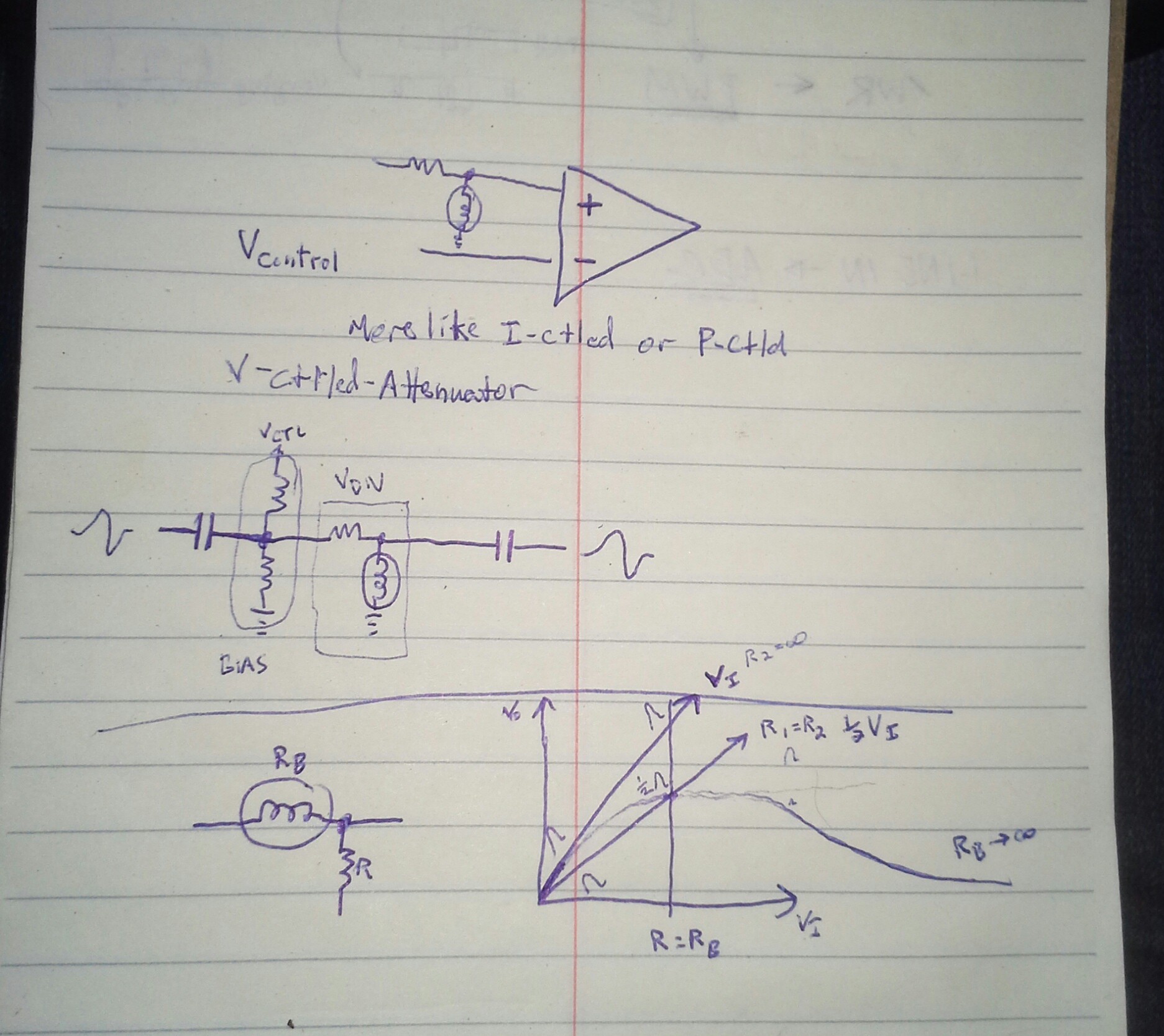
oh snap, what's this a voltage-controlled attenuator?
...
Search-fu is failing me... Seems there should be a circuit-model for these things, instead the best I've found is this:
http://physlab.org/wp-content/uploads/2016/03/Planck_ref8.pdf
Though, graphing the [very limited] points, it seems resistance is nearly linear with voltage.
Am darn-near certain I'd read about lightbulbs used as circuit elements in old-tech, just a few friggin' days ago. The obvious use as a fuse/current-limiter. Though, I vaguely recall hearing they were used in things like oscillators... and Not as an indicator.
I also recall reading mention of their use in synchronizing AC sources, If the phases are aligned, the bulb goes off, if they're not aligned, the brightness indicates the phase-difference. I definitely recall seeing this setup in a hydro with two generators, long long ago. Very cool, but not the same as using it as a passive component...
But those curves!
Seems unique, usable, if not *useful* in analog math, but I'm not finding it... Voltage-controlled attenuation is the best I've come up with so far.
OTOH, since heat takes time to build-up and dissipate, it seems this has similar characteristics as capacitors (storing electric-fields), inductors (storing magnetic-fields), and light-bulbs storing heat-fields. Current-memory, kinda like inductors, except with the opposite effect, resistance *increases* with current. Memory. Hmmm.
Friggin' Visual Data Bits! Like magnetic-core memory, or capacitive DRAM!
Yep... am already designing the read/write/refresh circuitry... relays? "Holiday Festive Lights"? Yeahp.
We're talking a frame-buffer *and* display in one.
A bit, maybe, like my history of abusing TFT panels ["avr-lvds-lcd"].
And, a use-case involving persistant-IR-imaging. Imagine placing your hand on a grid of lightbulbs,
Discussions
Become a Hackaday.io Member
Create an account to leave a comment. Already have an account? Log In.
FYI: I've started a new project! Thanks for all the comments, here!
#Incandescent RAM
Are you sure? yes | no
'Ping'
Great idea dude :-)
Are you sure? yes | no
Thankyah, Sir!
Are you sure? yes | no
Your incandescent bulb reminds me of PTC thermistors used in ceramic heaters that auto-stabilize at a fixed current and temperature. But their resistance doesn't go up until it reaches the Curie temp--at which point it starts to rise quickly. Its filament probably doesn't have a Curie point (tungsten being paramagnetic), but if the filament is an alloy or doped with something else, maybe an oddly low or flat resistance could also be explained by being under a Curie point somewhere? Just a guess--am probably wrong.
I almost tried using an NTC thermistor to do the reverse: limit the initial startup current of a DC motor which kept overloading my power supply (but was otherwise fine during normal running). I decided to just use slow-start PWM instead, but the idea of using passive "resistors" to do things that seem active and dynamic is intriguing.
There was a paper last year called "Could a Neuroscientist Understand a Microprocessor?" where some scientists tried to analyze a 6502 running Donkey Kong, Space Invaders, and Pitfall using neuroscience techniques, examining the activity of each transistor to look for correlations. Not much meaningful information was discovered, yet interestingly, they didn't find a reason why this technique would work any worse than it does for the human brain.
Similarly, I wonder if someone might find something meaningful one day, some type of universal pattern, in the flickering lights that might be emitted from your incandescent heat-based volatile memory, or Dr. Cockroach's CdS/LED Light Logic, or even those Dekatron tubes.
Are you sure? yes | no
Oooh, This is some interesting reading. I was thinking about it for a bit, then was suddenly innundated with comments over at the new project-page: #Incandescent RAM
PTCs and NTCs look quite useful for this project, admittedly I had to look up the terms. Thankyah for the deeper-explanation! Looks like they, too, can be used as memory. Curie-points and current-flows through, essentially, an inductor is quite the mental trip.
Not sure what to think about neuroscientists and transistors... I guess neurons work less on values/states and more on pulses and timing. From what I understand, transistors and electronic components have been used to simulate neurons... even from the very early days of electronics, probably even before binary was a thing. There must be some reason so much has gone "digital," but even analog differs from neuron-firing, which is analog-input, with binary-output, and importantly, the temporal alignment of those binary 'ones'.
Interesting tangent, this is quite similar in concept to #Floppy-bird , which stores binary data as impulses whose temporal-placement determines the value. Never thought of that! Weird!
(LOL, this log *is* for floppy-bird. Boy I've gotten sidetracked!)
Yeah, @Dr. Cockroach 's #Light Logic surely helped inspire this. Blinky things are almost universally-great, otherwise we wouldn'ta bothered mapping stars eons ago :)
Are you sure? yes | no
Ah, cool, using an NTC to ramp up the current through a motor! I dig it.
I agree whole-heartedly, using passives for seemingly-active purposes is pretty cool (or hot, depending on the power ;)
Them old-timers were pretty clever back in the day, and now I guess we get to rediscover their knowledge as it decreases in common-knowledge in favor of newer/"more-efficient" tech.
I think there may be some balance where old-inefficient-tech is actually as-"green" as the devel-time, silicon-creation, etc. necessary for more-efficient tech...
I think it would be unwise for us to lose these skills!
Are you sure? yes | no
Everything old is new again... look up the WITCH computer and how it used Dekatron tubes... ;)
Are you sure? yes | no
Gah! my search-fu is still failing me today! I was aware dekatrons store states, but had no idea they were used as memory.
Can't quite piece together *how* the present state is read-back, a "charge" is moved from one "charge well" to the next by, essentially, dragging it electrically, like one might drag a magnet across a table by sliding another underneath it. But what actually turns that "charge" into something readable, another electric signal, I can't find. Am thinking the vacuum-tube nature makes this an active process... grids and heaters and electrons flying through vacuums/gasses... probably an amplification involved. Intriguing!
But... not at all like incandescent memory, which stores a value in white-hot near-molten metal and reads back a measure of the seemingly endless twisted path through hellish fiery terrain and suffocatingly fire-retardent-laden atmosphere the poor electrons had to traverse... I feel like there must've been a highly dangerous ring involved ;)
Here's som'n cool, thanks for the search-path!
https://hackaday.com/2016/03/08/thanks-for-the-memories-touring-the-awesome-random-access-of-old/
Are you sure? yes | no
Your answer is at that very link. Dekatron section, last sentence of the second paragraph.
Are you sure? yes | no
Ah, guess "separate cathode" didn't quite register as an explanation of functionality. Sounded to me like essentially saying "there were also pins for readback."
I'll put my thinking cap on, thanks.
Are you sure? yes | no
Sometimes old school still rules :-)
Are you sure? yes | no
Indeed!
Are you sure? yes | no