Close
0%
0%

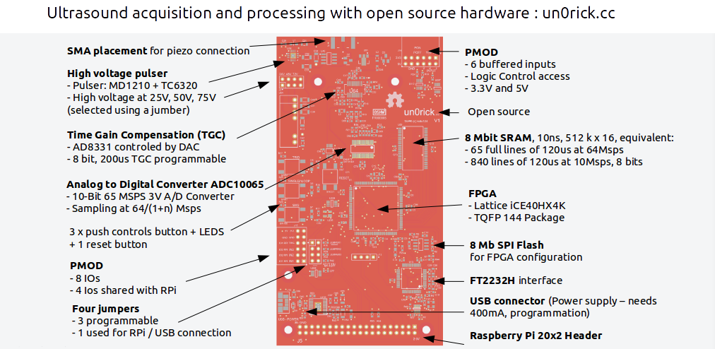
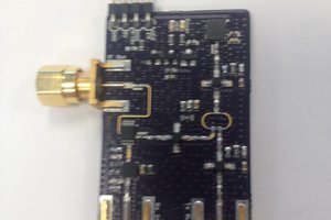
un0rick - an ice40 ultrasound board

A hx4k lattice fpga based pulse echo board, yosys compatible

Public Chat
Similar projects worth following
Non destructive testing and imaging ultrasound modalities have been around since the '50s in . More and more ultrasound-based initiative are emerging, mostly focusing on image processing - while hardware has been left behind. Several teams have produced succesful designs for the different possible uses, mostly efforts from research laboratories. Most have been used on commercial US scanners, traditionaly used as experiment platforms, but they are not cheap, and yield very little in terms of data access and control. Others have been developped in labs, but, sadly, very few have been open-sourced. Let's tackle this!

un0poly.pdf

This PDF details the un0rick board.. but is also a zip that contains its source =)

Adobe Portable Document Format - 4.60 MB - 04/06/2021 at 11:03

Preview
Download

  • HV Mux - 8 TX/RX transducers

    kelu12405/05/2021 at 21:02 0 comments

    Been working on a MAX14866 MUX - allowing to drive 8 transducers separately on the Tx and/or Rx path. Not so bad, I've managed to plug a 5-ring annular element and run some tests. I assume some connections need to be reviewed, as not all paths seem connected.

    Setup. Inclusion at 15-30mm depth.

    Images for 25 pairs of piezos (5 piezos, 1TX/1RX each time)

    Filtered

    Details of the bottom of the phantom at 50mm

    Some fun ahead!


  • Easier to use: USB only, and VGA output.

    kelu12404/06/2021 at 11:08 0 comments

    Long story short, the board does pulse echo in live, can output to host via USB, with visualisation through a VGA connector.

    You can read more on the website

    lit3-32

    Also.. the pHAT version is coming up, with moar gain !

  • a pHAT is coming

    kelu12401/12/2019 at 21:20 0 comments

    An ice40 up5k-based board:  simplified BOM, fewer parts, using the up5K internal ram for storage. Curious to see it in real life =)

    And here's a first render of the pHAT.. some wrong formats but still gives an idea! With two SMAs too, and external connectors for high voltage sources.

    Onboard has 0 to 40V source.

    More info on https://github.com/kelu124/echomods/tree/master/matty/minie

  • Night sky

    kelu12409/01/2018 at 13:49 0 comments

    Some more tests with a probe.. this time from kretz technik. Raw acquisition yield interesting signals.. Doesn't it look like a night sky ?

    The spectrum seems to contain good ultrasound (with a fair dose of noise) - the signal is between the blue lines, between 2.2MHz and 4.2MHz:

    Which yield a classical wirephantom image.

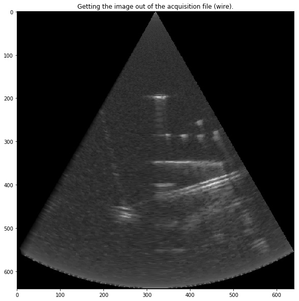
    See more on the notebook -- https://github.com/kelu124/echomods/blob/master/matty/20180901a/20180901a-Client.ipynb

  • Doubling the speed, to 128Msps

    kelu12408/14/2018 at 21:54 0 comments

    Breaking the wall of sound! un0rick can sample at 64Msps but ... one can offset the start of an acquisition by half a cycle. In practice, it means one can do two acquisitions, with one delayed by half a cycle, and interleave the two series. In practice: getting 128Msps acquisition speed!
    In picture, it seems quite nice. The signal is loud and clear!

    And notebook at https://github.com/kelu124/echomods/blob/master/matty/20180814a/20180814a-Server.ipynb . Some improvement on the lib too, not perfect yet but someday better!

  • Working with classes / calibration of TGC

    kelu12407/22/2018 at 12:56 0 comments

    Objectives

    The objective of this experiment is to check :

    1. If class-oriented library works
    2. The TGC functionning, and its calibration
    3. Have fun introducing new class functions

    Resources

    Results

    Type of signal

    Curve of the gain

    Impact of gain on noise

    FFT - content of such a line

  • Production: validated

    kelu12405/23/2018 at 21:10 0 comments

    The good news is that I've just tested the production version and it runs fine. Images of the wirephantom look good (full doc):

    Now working on the data format, and, in anticipation of the first runs, I've started working on the documentation, including some nice visuals:

    What do you think?

  • Comparing modules and fpga board

    kelu12404/17/2018 at 20:35 0 comments

    Let's compare the acquisitions with the modules compare to the un0rick board. At a reduced speed for the un0rick, the acquisitions are quite comparable, showing similar acquisitions at 21Msps and 22.5Msps.
    Blue is from the raspberry board, red from un0rick.
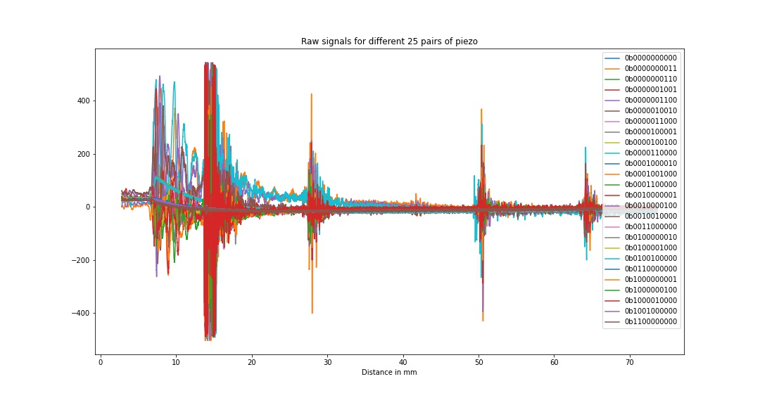
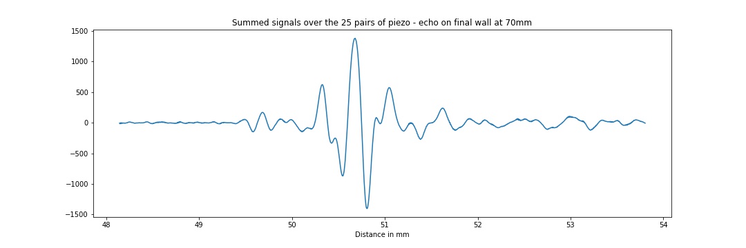
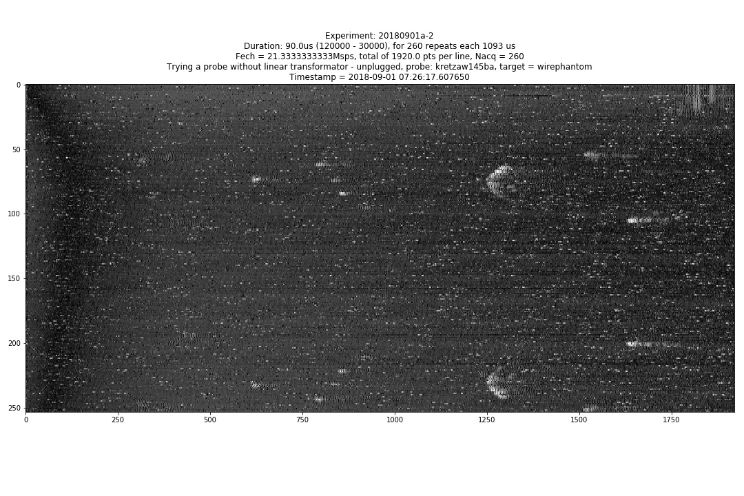
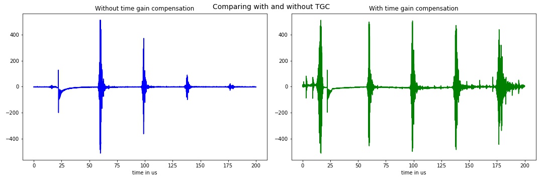
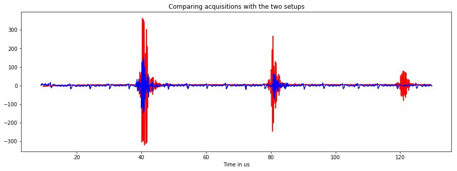
Now, going on the details of the acquisitions. we see that the level of acquisitions are higher (which is normal as the range of the un0rick gets data on 10bits, whereas the pHAT is on 9 bits).
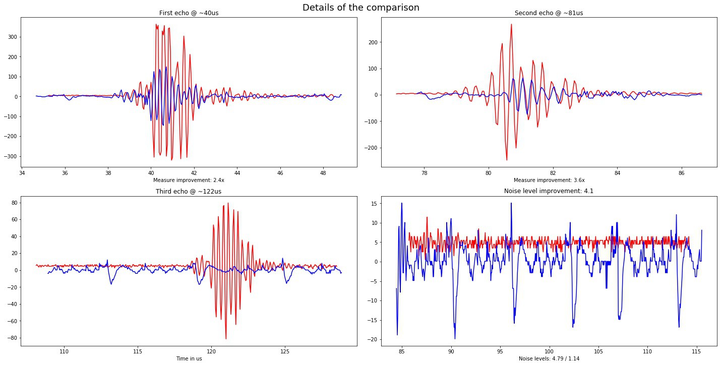
    Moreover, the last acquisition, at ~120us, appears quite nicely with un0rick, whereas it is off the radar on the modules.

    One can also see that the level of noise has improved by a factor of 4.. or more.

    But I'd need to be more rigourous to get precise numbers =)

    Log as usual is available.

  • Time gain compensation - check

    kelu12404/08/2018 at 21:35 0 comments

    Ultrasounds, traveling in the medium they image, are attenuated by the very same medium and the further they progress, the faintest the echo comes back.

    In order to compensate for this attenuation, the echoes are usually amplified by by a variable gain which renormalize these echoes.

    The plots below represent in blue, unsimplified signals, and, in green, the amplified signal, with a gain shifting from 0% to 100% in 200us. It seems that makes the echoes great again =)

    More in the log.

  • Retroengineering an ultrasound probe - part 1/X

    kelu12403/18/2018 at 20:57 0 comments

    I just got an interesting mechanical probe, a Bard Site Rite - piezo at 7.5MHz. The plug is quite simple, and digging into the cable yields 2 pairs of cable, one coax, a bigger cable with two "big" cables. I've made sure it's a mechanical probe. The aim is to try and see if I can connect it to my board and get an image.

    Good point for this probe is that it unscrews nicely.

    and even better, it has changeable heads!

    I assume two pairs of cables are for motors / actuators, coax is for the signal coming back (hence the bead). But how can I see that on the pins above?

    Going to search for the reference manual and other resources. I'd rather not unscrew the head yet!

    To be continued... possibly with a corresponding patent... Electromagnets?

View all 15 project logs

Enjoy this project?

Share

Discussions

Per Bandsholm wrote 03/08/2018 at 18:13 point

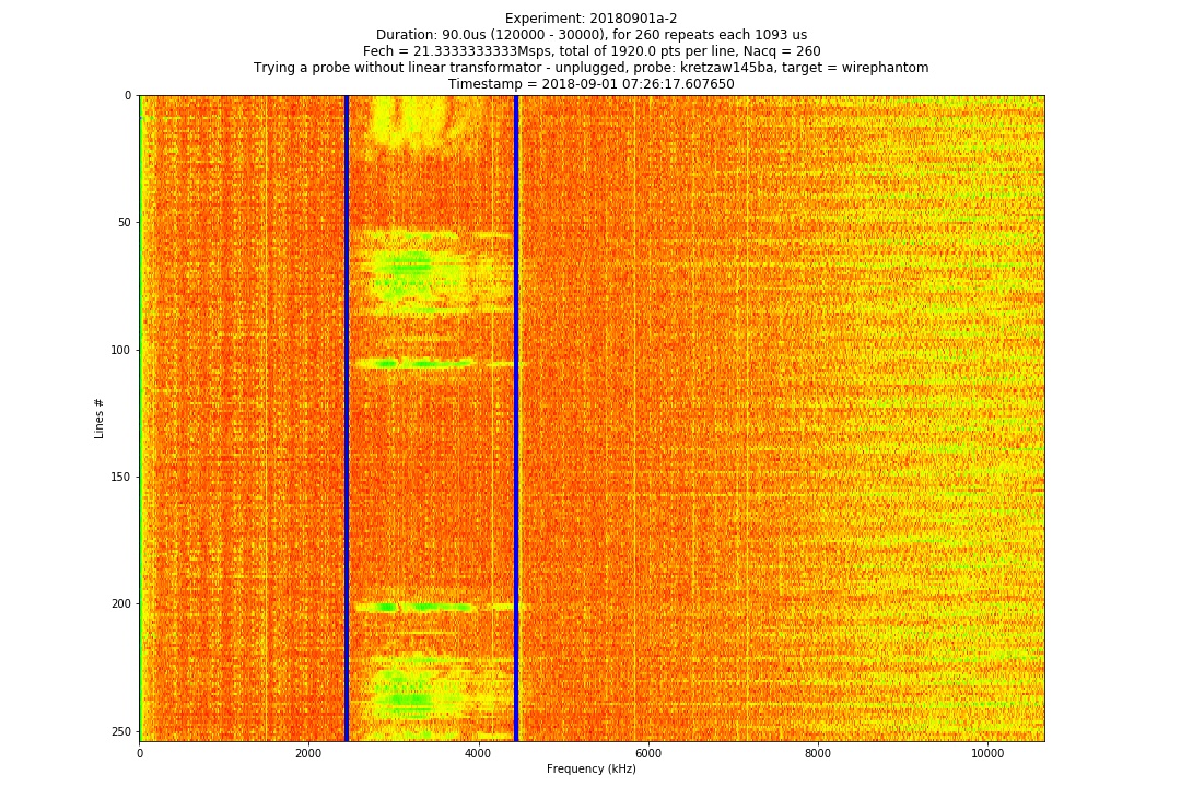
HINT: Can this be relevant instead of FFT...

http://www.soundid.net/SoundID/Papers/Detector%20Paper.pdf

  Are you sure? yes | no

kelu124 wrote 01/18/2021 at 18:55 point

  Are you sure? yes | no

Similar Projects

Does this project spark your interest?

Become a member to follow this project and never miss any updates