 Jean Simonet
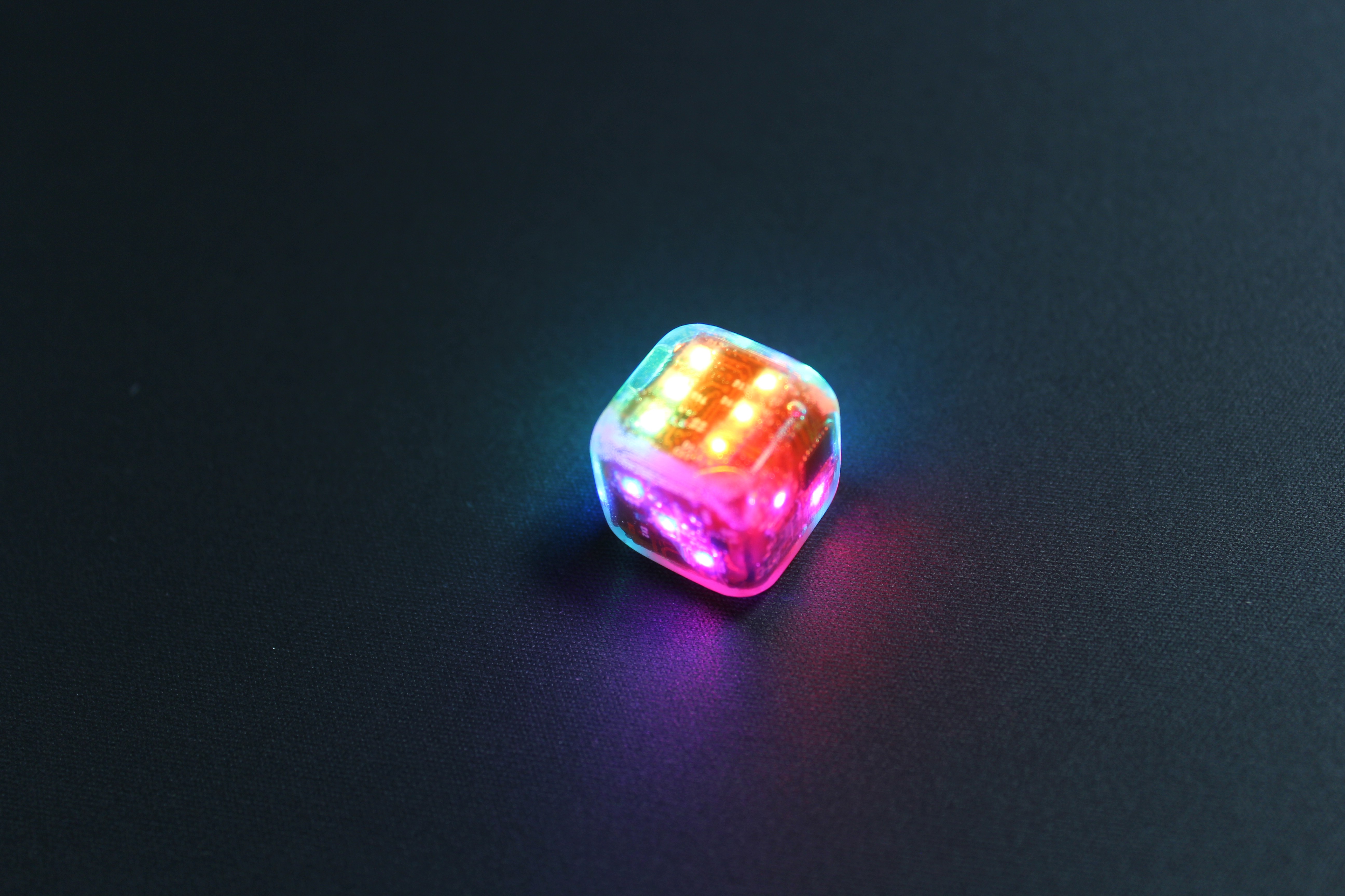
This is the next revision of the Electronic Dice. I've spent a lot of time putting it together, and it is really coming along!
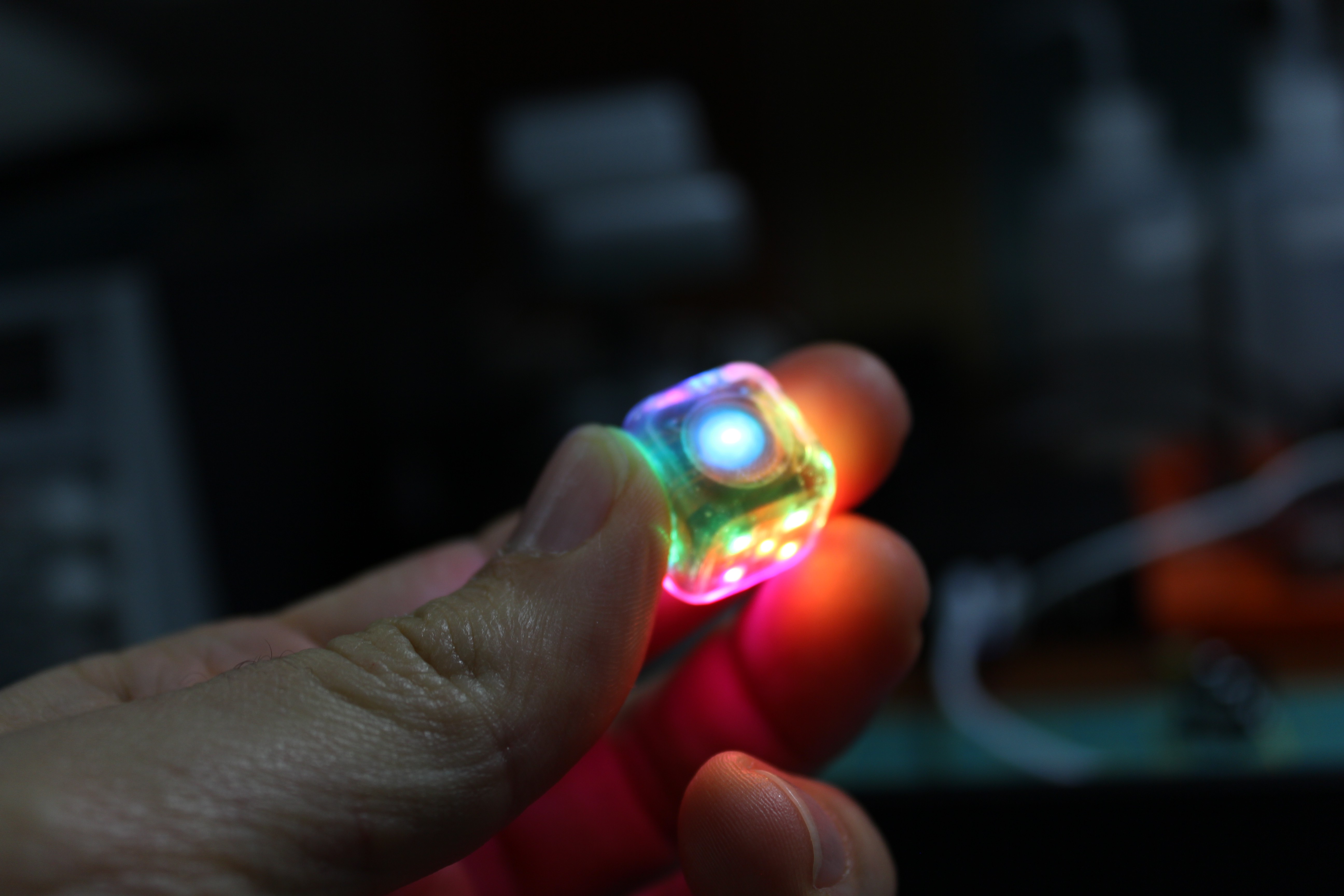
Looks pretty nice, doesn't it?
So first things first, this version is exactly 16mm, the same size as a regular dice. And as you can see here next to the previous prototype, it is also more rounded. It's amazing how much difference 1mm can make, both in how the dice feels in your hand, and how much harder it is to put together!
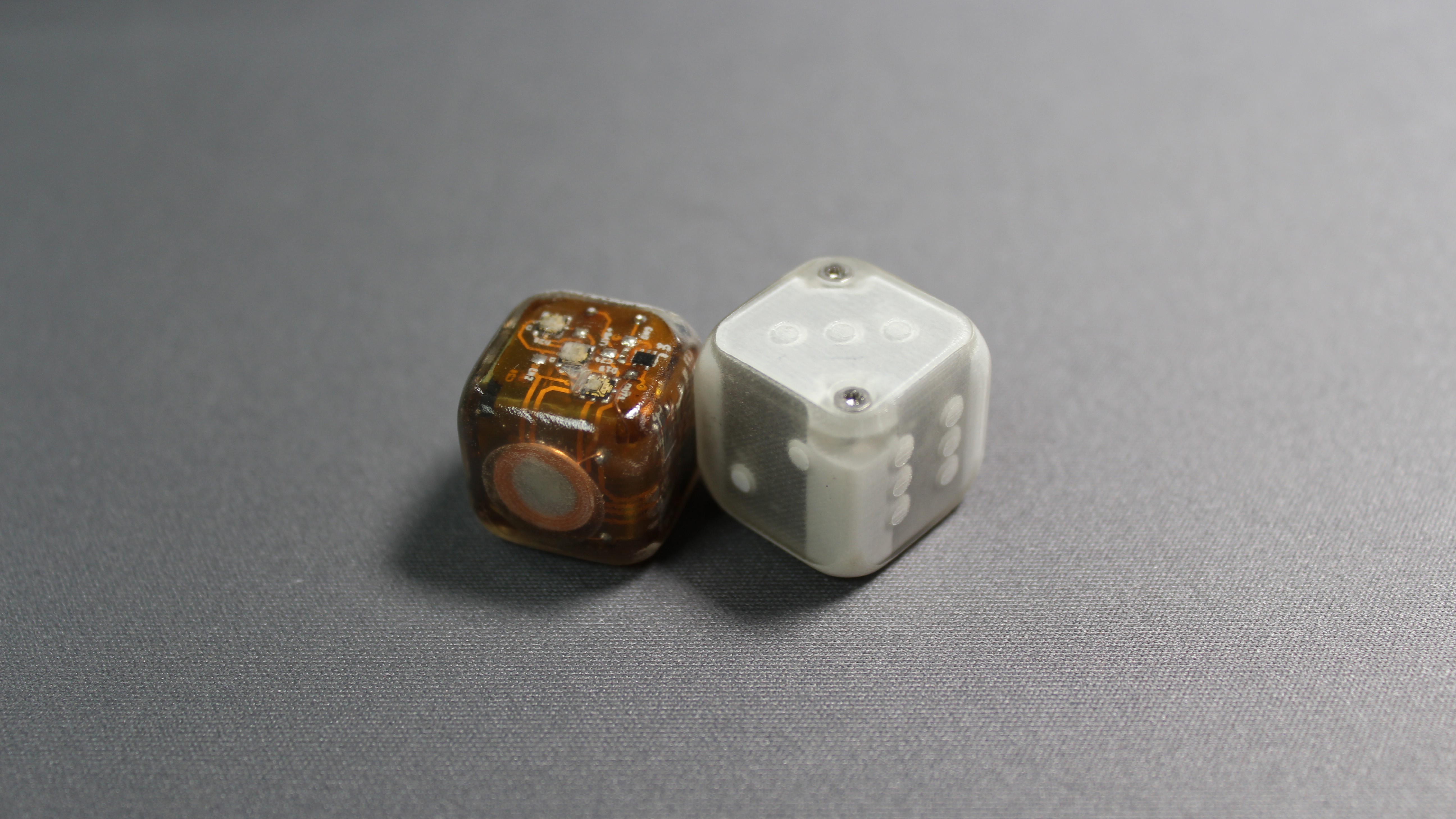
Of course, the other thing you might notice, is that this version doesn't have screws, or a removable lid in fact. Actually, this is a great example why sharing your work matters. In the last video, I specifically mentioned how I wasn't able to find a rechargeable battery small enough to fit in the case, and therefore why I had to design the dice with a removable lid.
Well, somebody mentioned searching for Bluetooth headset batteries, and sure enough, as soon as I started plugging in the right keywords, I was able to find small lipos on Alibaba.
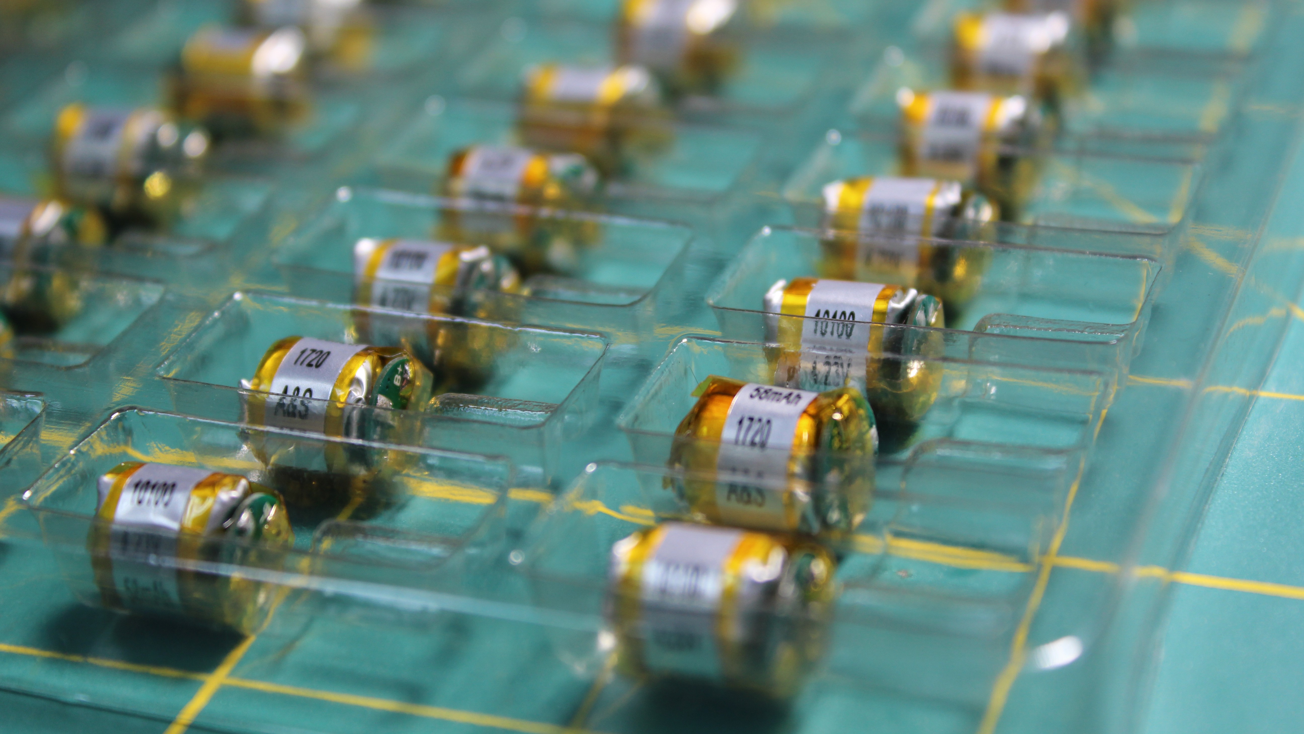
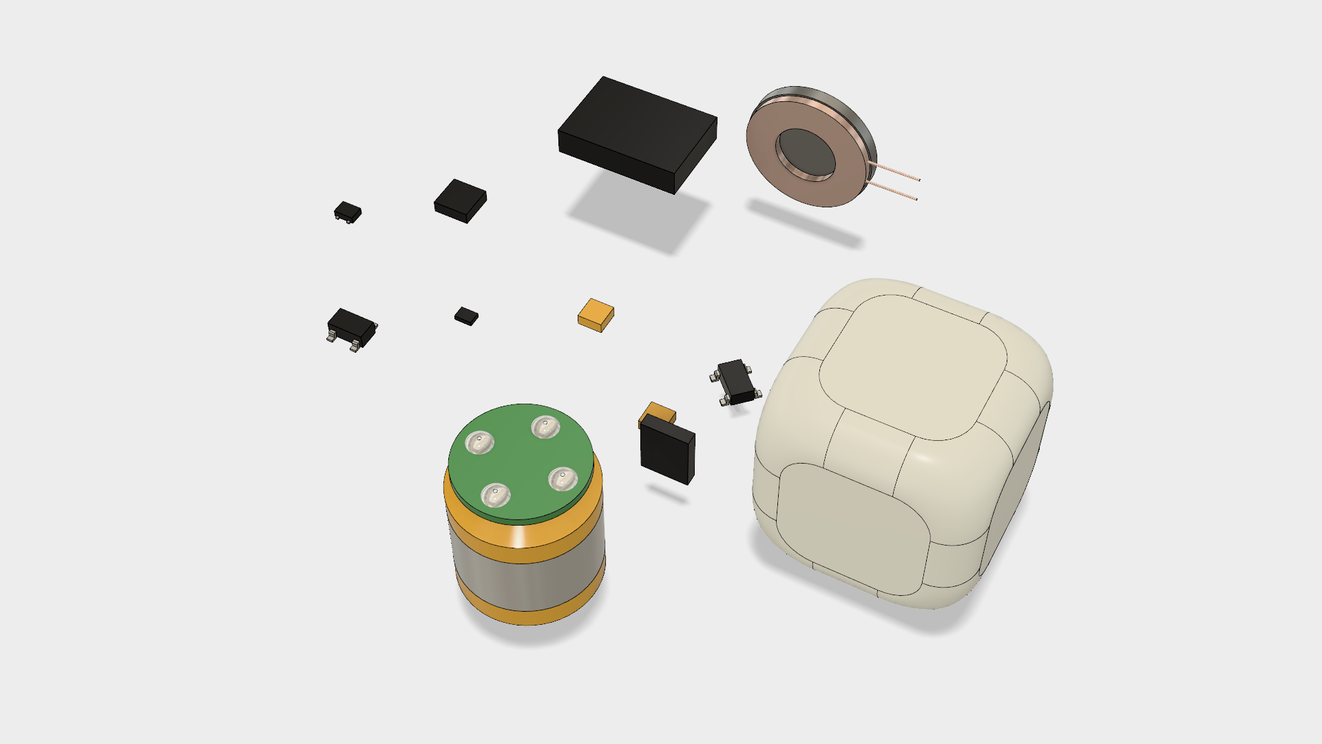
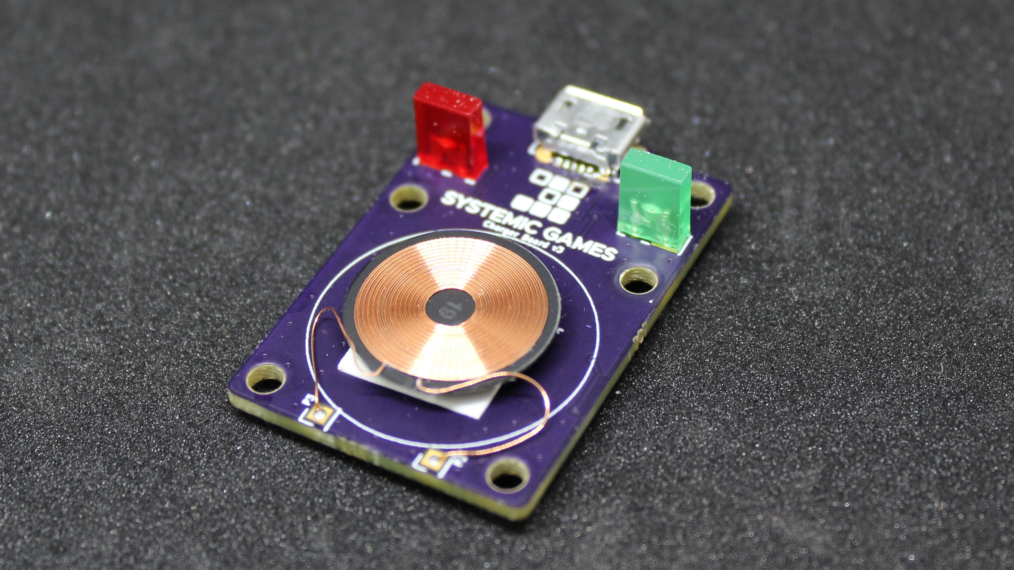
These things are nice, they can supply enough current to light all the leds at once, although, obviously, that would drain the battery really fast! Of course, having a rechargeable battery isn't much use if you can't actually recharge it, and this is how I got to research inductive charging. This was a completely foreign area for me, and in fact it turned out to be pretty complicated. Not being all that comfortable with analog circuitry and magnetics, I looked for two things: a wireless coil that could fit inside the case, and whether there were integrated chips that would take care of the transmitter/receiver pair.
Well it turns out, Qi charging is pretty popular these days, and so there are several integrated chips that will take care of everything for you. I even found a Texas Instrument chip that would rectify the inductive current AND charge a lithium-ion battery, and all in a tiny package too, the bq51050.
The coil was also not too hard to find, a quick search on Digikey turned up several candidates.
After that, it was ‘mostly’ a matter of following the application notes on the datasheet, using the formulas they provided to compute the values of certain key components and giving it a try. I was hopeful that a standard Qi charger would just work with the dice, but unfortunately it didn’t.
It turns out that the two coils involved in the transfer have to be pretty well matched in order for the magnetic flux to induce enough current on the receiving end. So if my receiving coil was going to be a lot smaller than normal, then my transmitter coil needed to as well.
The other thing I found out, was that when you scale down the coil geometry, you need to scale down all of it, including the distance between the coils. It’s obvious in hindsight, but it took me a while to realize that. And so, while with standard Qi chargers you the coils can be 3mm appart, with a 10mm coil, they needed to be less than 1mm apart to be able to transfer enough power.
This posed several problems with the design which I’ll get into in a bit. First let’s finish the tour.
Flex PCBs
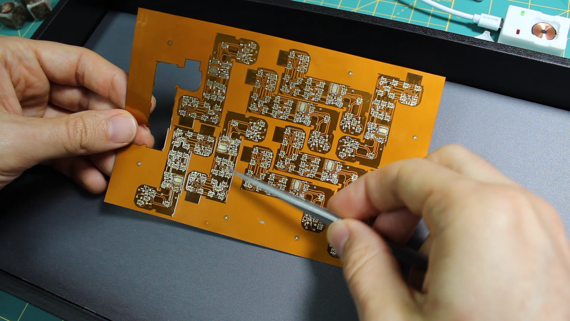
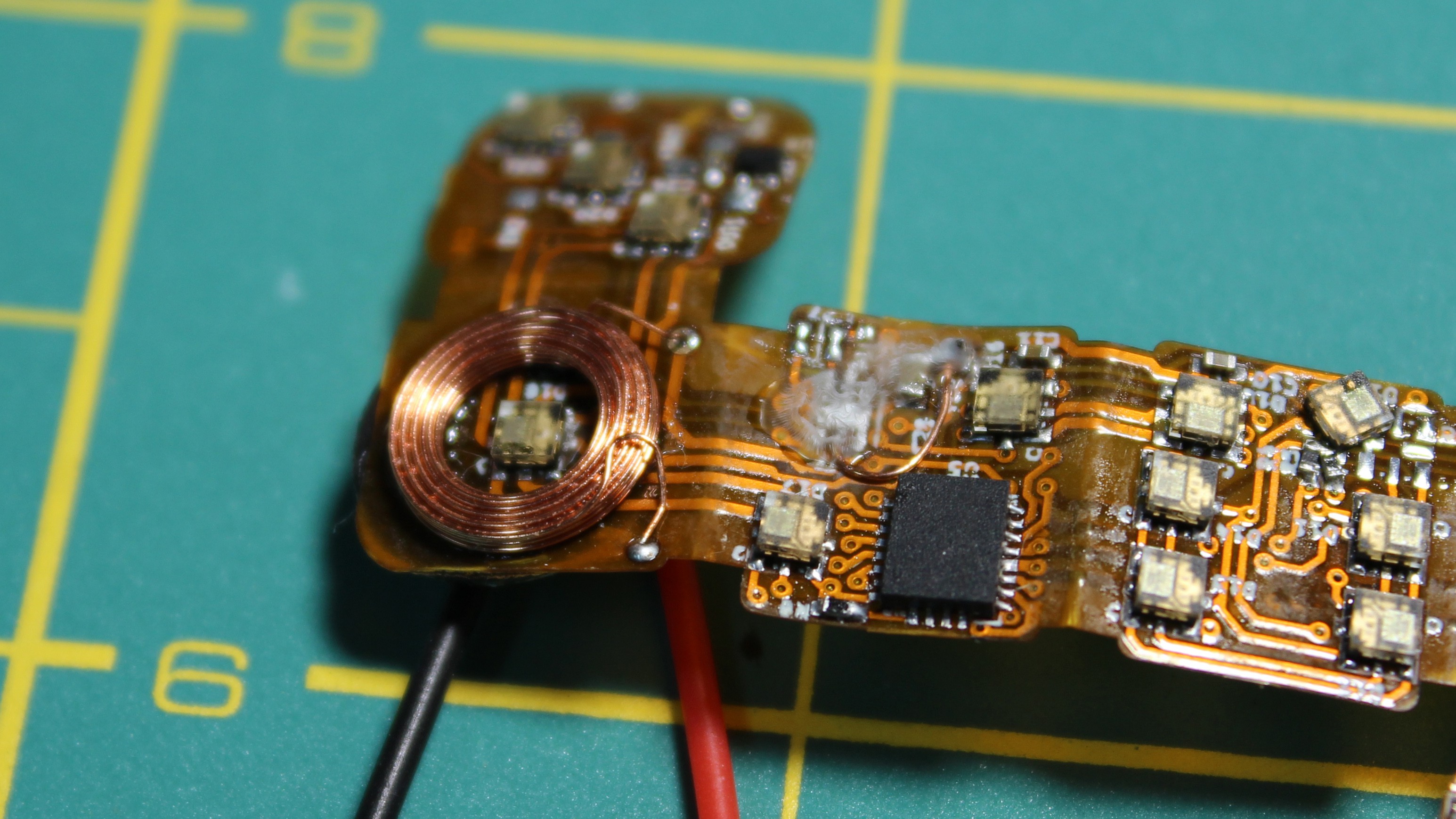
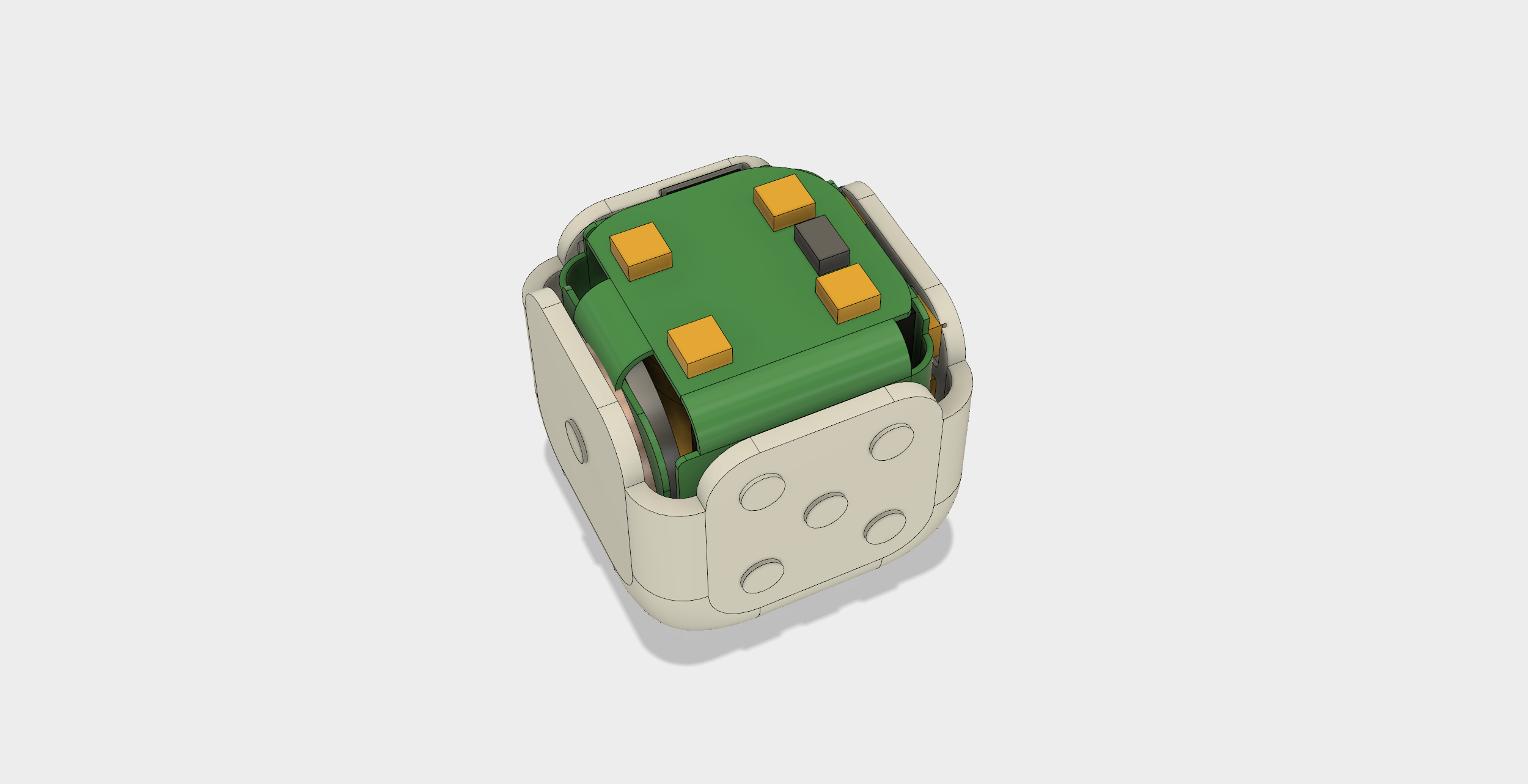
So, the principle is the same as with the last prototype. The components are soldered onto a flexible pcb, that is then folded and placed inside the case, with the LEDs facing outward. The battery fits in the middle and then the top flap folds back in to finish the cube. This small panel here was made using GoldPhoenix batch flex service.
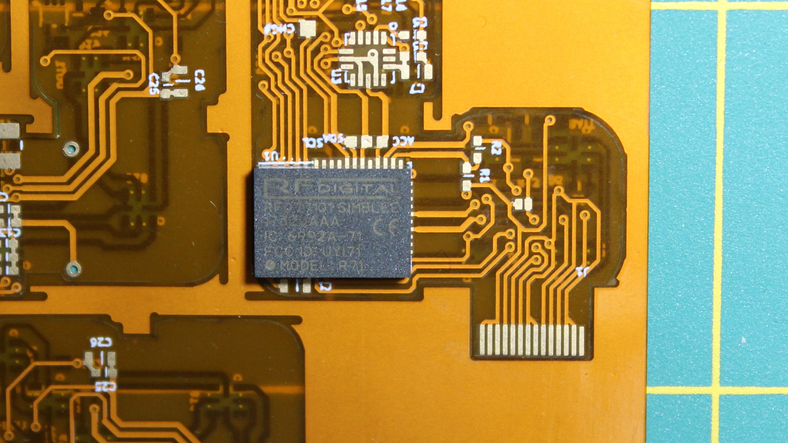
The main microcontroller is again the Simblee, internally it is just an nrf51, crystal and chip antenna in a single package. Now, while the simblee has been really useful to get up and running, they provide an arduino-compatible toolchain and libraries that make writing your first bluetooth program a breeze, I think for the next version I’ll actually switch directly to a nordic chip (the nrf51 or nrf52). RFDigital, the creators of Simblee, was acquired by somebody else, and ever since, support has been really lacking. Plus the chips are unreasonably expensive for any sort of batch manufacturing.
LEDs
The leds are APA102 2020. These little guys are really great. The colors are amazing and they are very easy to control. They are also really simple to connect, as they are meant to be daisy chained. This turned out to be a huge advantage, as it reduced the complexity of the routing. In order to get affordable flex pcbs, you really need to stick to two layers, and with my size constraints, not having to route a complicated led matrix really helped! Of course, APA102s are a little more expensive than similar ‘dumb’ RGB leds, but thanks to Alibaba, I was able to find some for a decent price.
Now there are two issues with the APA 102s, or at least the ones I got.
The first one was that they draw a full milliamp of current even when off. I think what’s happening is that the internal PWMs that modulate the intensity are just ‘dumb’ and remain on all the time even if the intensity is 0. But with 21 leds, it means that the dice would constantly draw 21 mA from the battery, which would kill it in 2 to 3 hours for sure. To remedy this, I added a small transistor to cut off the power to the LEDs altogether, and had the microcontroller toggle that transistor when it went to sleep.
Unfortunately that was NOT enough. This one stumped me for a bit, but the best I can explain it is that the LEDs will drain current from the data and clock lines. So in order to make sure the LEDs don’t draw any leakage current, I had to make sure the data and clock lines were low before going to sleep.
Eventually though, I was able to get the current draw down. I still think there is some work to be done to minimize the current wasted in pull ups and pull downs in other areas of the circuit, but again, for this prototype this was good enough!
Power Circuitry
For power regulation, I was planning to use a small buck converter to get the Lipo voltage down to 3.3V, but ended up having stability issues (that I still haven’t quite sorted out) and ended up just ripping out the whole thing and powering the microcontroller directly from the Lipo battery. It is technically slightly outside the recommended range but it seemed to work, at least for a prototype.
The last IC on the board is the magnetic switch. The idea was to insert magnets in the dice’s carrying case, so that they would turn off while being transported. You don’t want the dice to light up and drain their battery for no reason. I had the magnetic switch connected to the power buck converter, so that it would turn off all the logic whenever a magnet was present. Unfortunately, turning off the power means that the LED control lines become floating, which, in turn causes the LEDs to turn on to arbitrary colors. Not acceptable…
So what I ended up doing was wire the output of the magnetic sensor to the microcontroller instead, and handle the ‘don’t turn leds on’ through software. It’s not as elegant a solution, but it did the trick. The magnet triggers an interrupt that in turn causes the micro to turn the led power off, set the control lines low and go to sleep.
I think that covers all of the internals! Let’s look at the design and assembly some more.
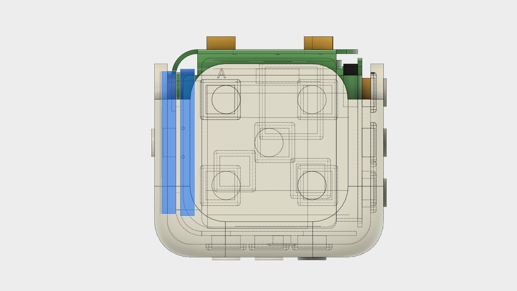
Fit Up
Unsurprisingly, for this next revision of the dice, I restarted the design from scratch. I wanted the dice to be exactly 16mm and have much more rounded corners. Well, you won’t be surprised to hear that it made the layout of the board quite challenging. Even though the leds are daisy chained, connecting all of them is slightly more complicated than I made it seem with the schematic. In the schematic it looks like there are only two wires going between each led, but of course, that’s ignoring power and ground. And unfortunately, the power and ground pins are not quite as conveniently placed that you can just connect 4 pins to 4 pins.
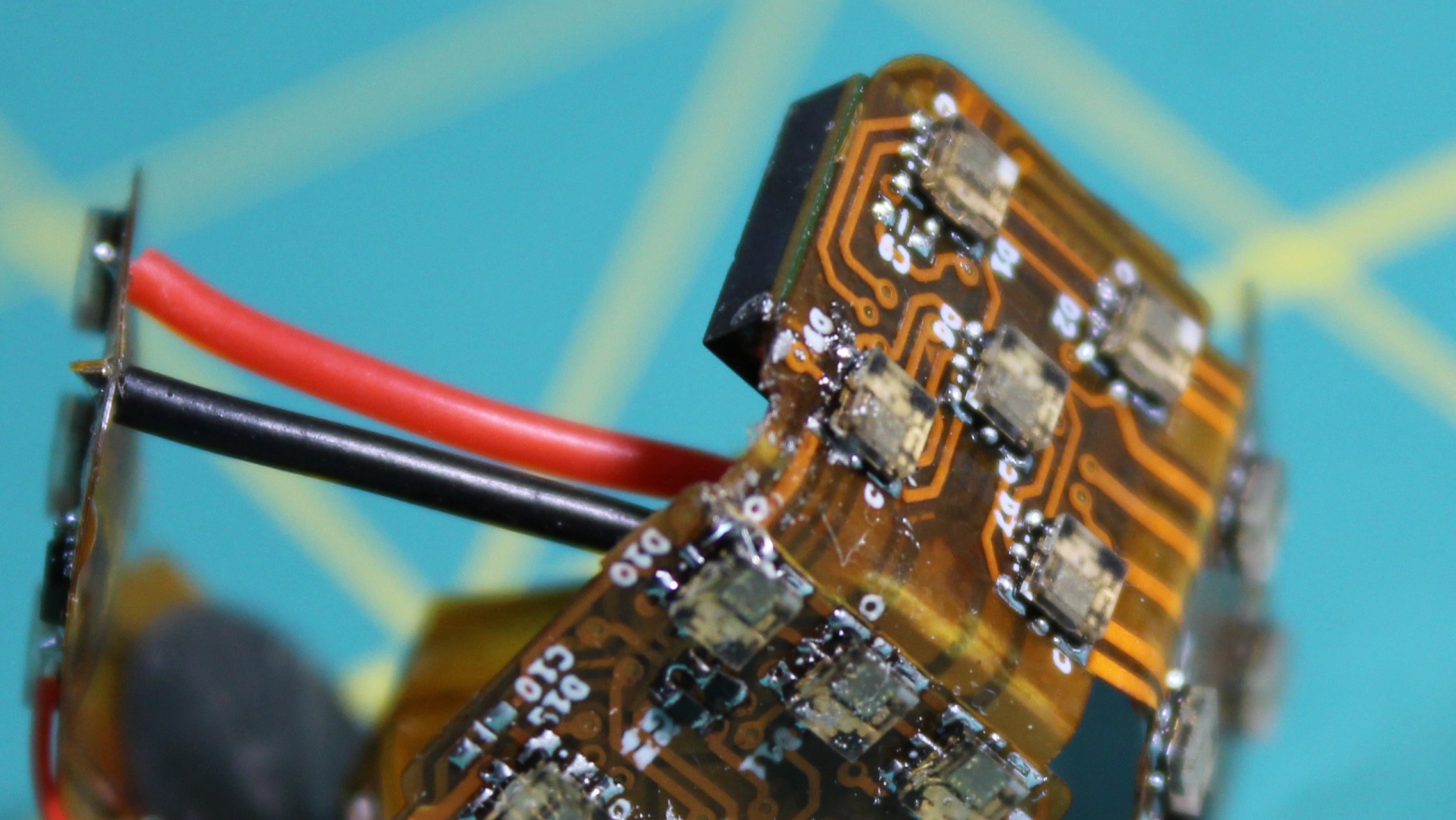
The other complication was that the board gets bent, and, aside from the obvious fact that I couldn’t put any component in the bends, the bends themselves put an extra amount of stress on the copper traces running through it, especially if you have a pad near a bend. The chances of causing a crack in the copper are really high. But, I didn’t really have a choice, the leds are pretty big and the dice really small.
So I tried to keep the traces going in the direction of the bend. I couldn’t, however, keep pads away from the bends, there just wasn’t room.
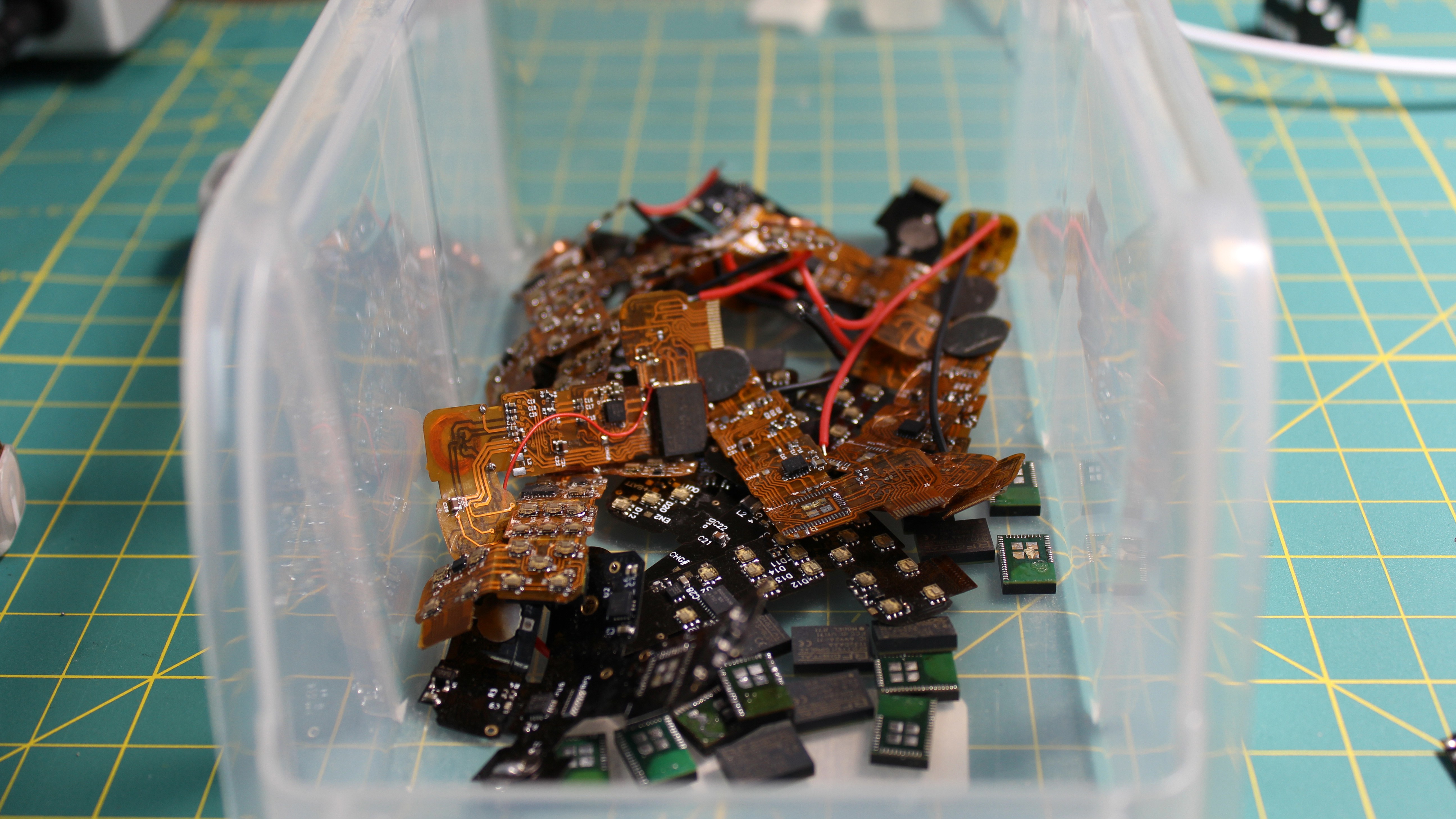
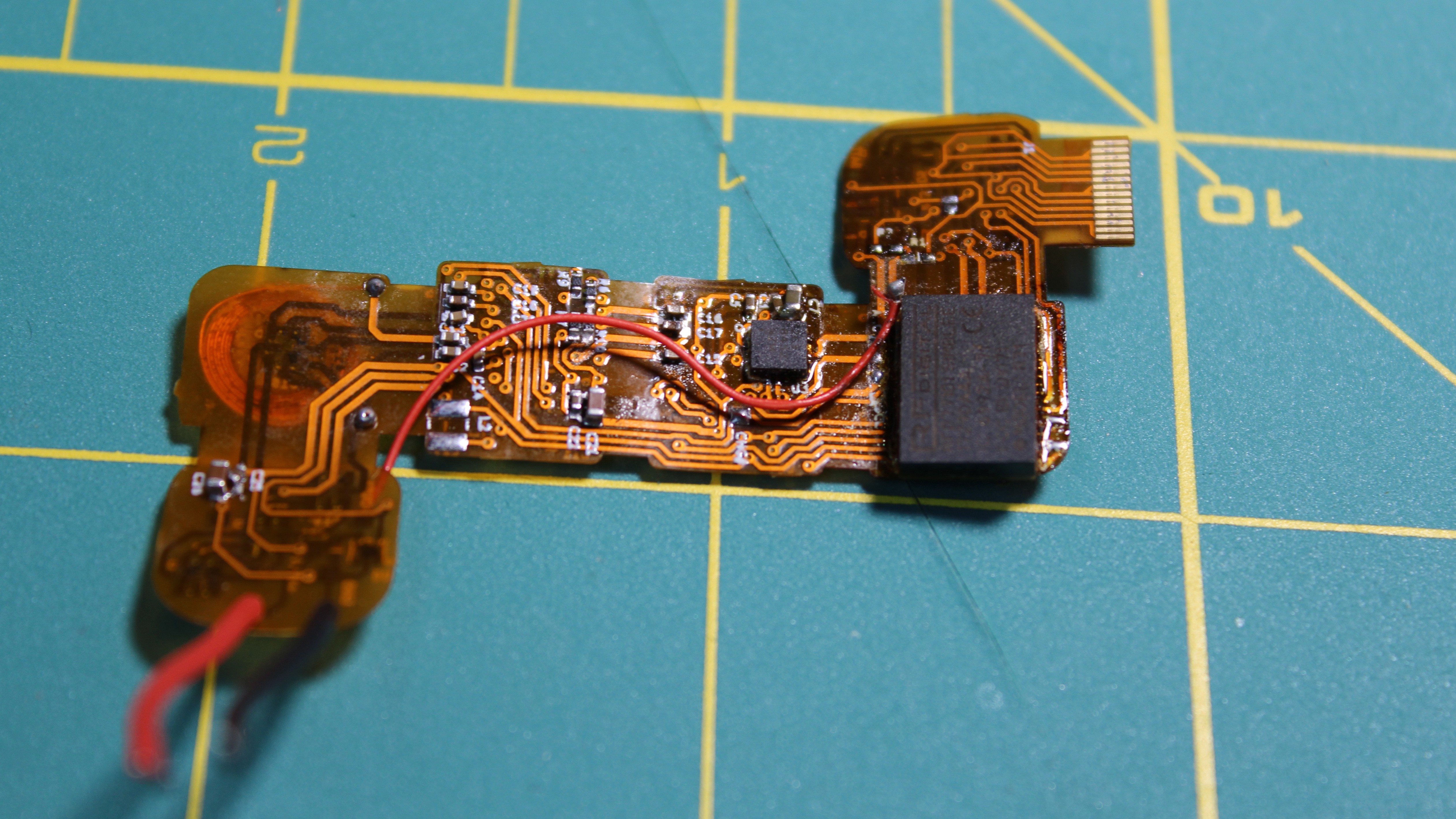
Annnd, of course, that did turn out to be a significant problem. I had a ton of boards start failing once I bent them to fit inside the case. Eventually I put together a small bending jig and tried to stress the boards as little as possible. That meant solder and test and program everything with the board flat, then bending the board with the jig, trying to concentrate the bend in the ‘safe’ areas, wire up the battery and drop the whole thing in the case in as fast a motion as possible.
To be honest, my success rate was pretty low, and when each board take around 4 hours to hand-solder and assemble, it’s pretty soul-crushing to have it just stop working on the next to last step. The worst part when that happened was that any attempt to get the board back out to try and fix the traces would inevitably cause stresses in another spot and cause some other crack to appear. Needless to say that this I will need to spend some time finding a proper solution to this problem, but anyway, obviously I did manage to get some of the boards fully assembled and working.
Inductive Charging
Remember when I mentioned scaling down the inductive coils for the charging circuit, and specifically how the coils needed to be much closer than with traditional Qi chargers? So yeah, it turns out that the only way to get the coils close enough together was to move the receiver coil all the way up against the case. Actually, even closer, I had to make a pocket so that the coil would be 0.5mm from the outside plane.
Of course that’s all fine and good except I still need at least one LED on each side, including the side with the coil. And to make everything even more complicated, the coil needs to have a ferrite backing, to focus the magnetic flux as much as possible…
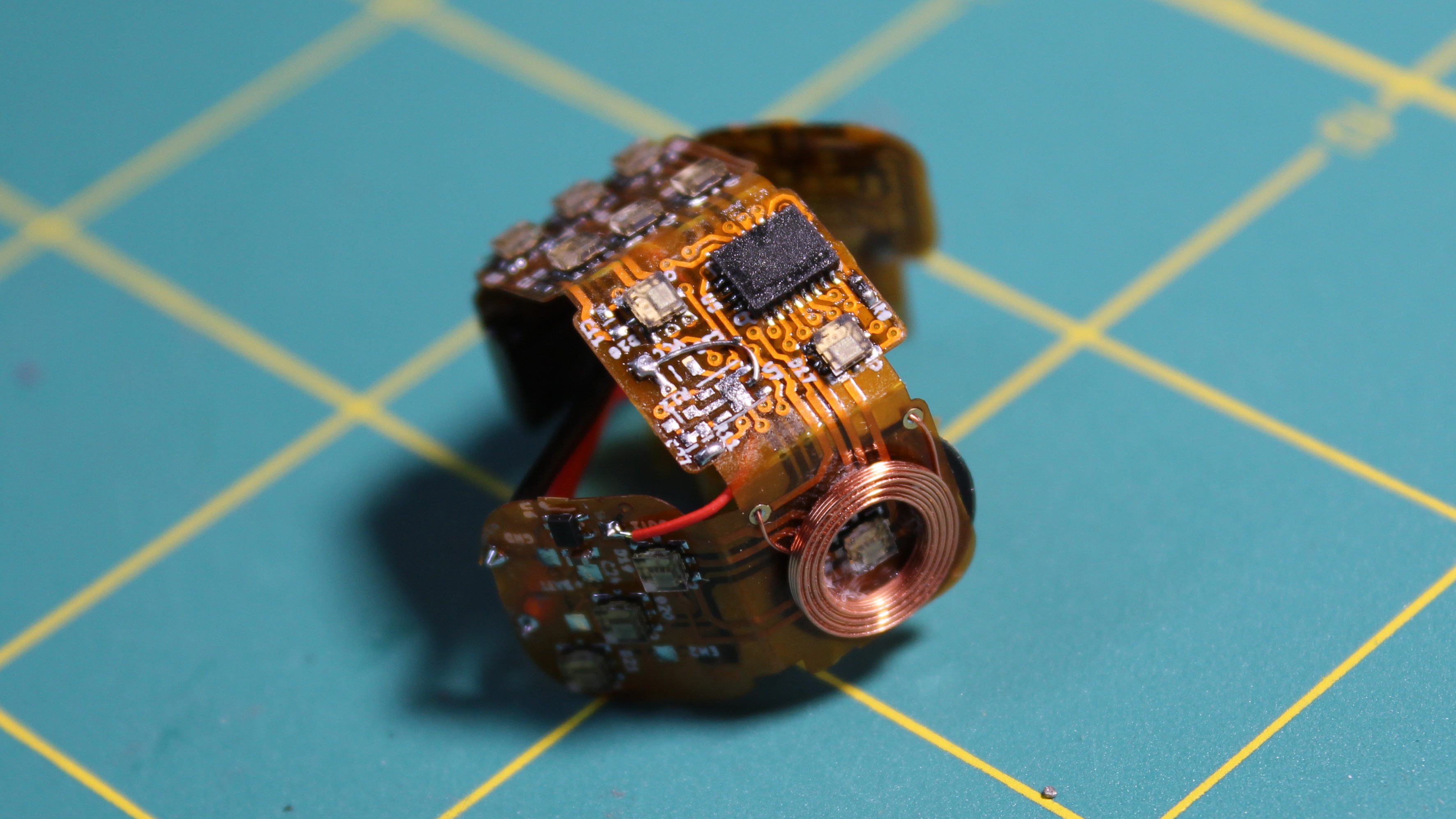
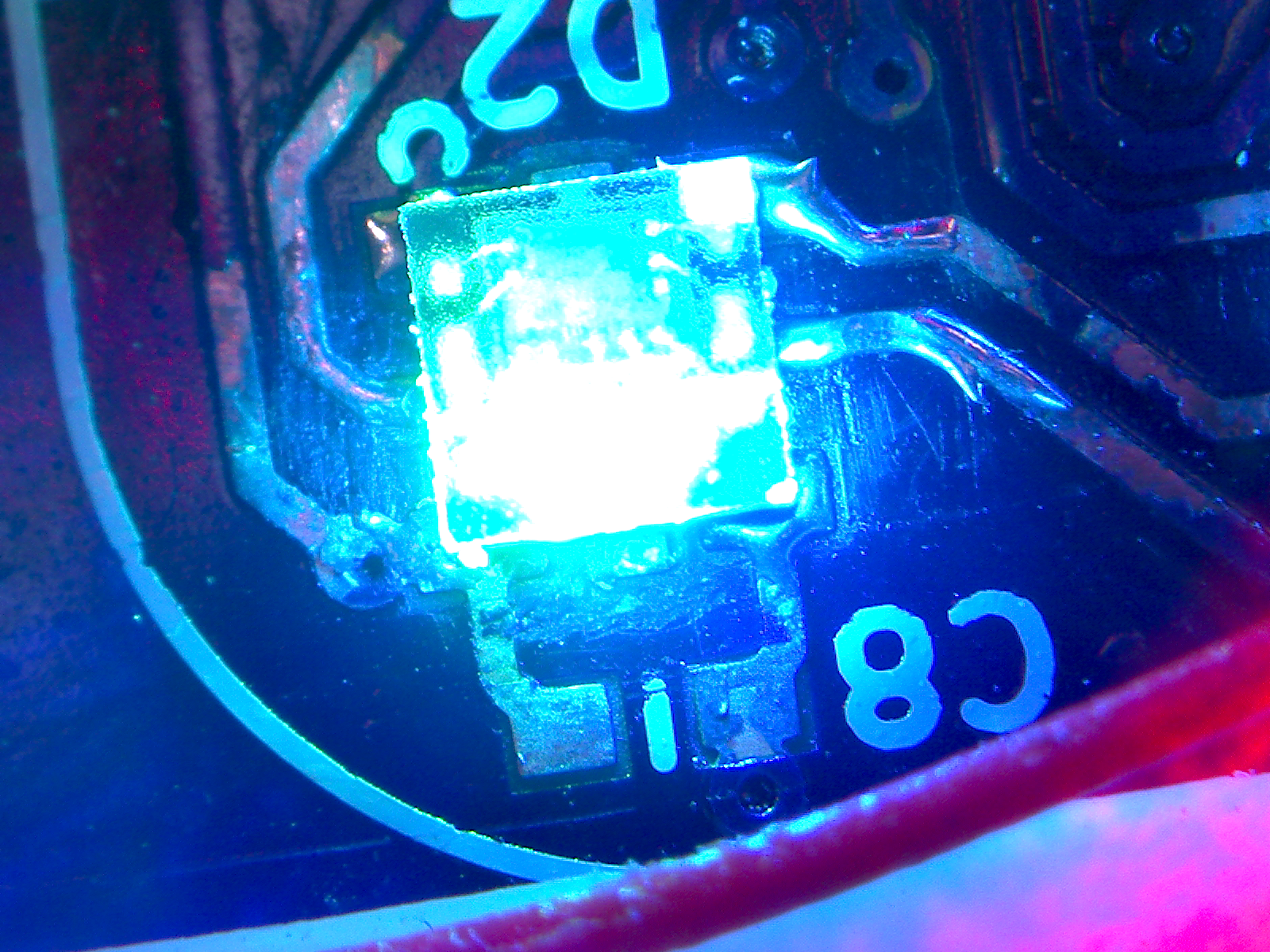
As it turned out, I got lucky, the APA102 led can fit inside the coil, and it wasn’t *too* annoying to pull the ferrite backing off the coil so I could glue it to the other side of the pcb.
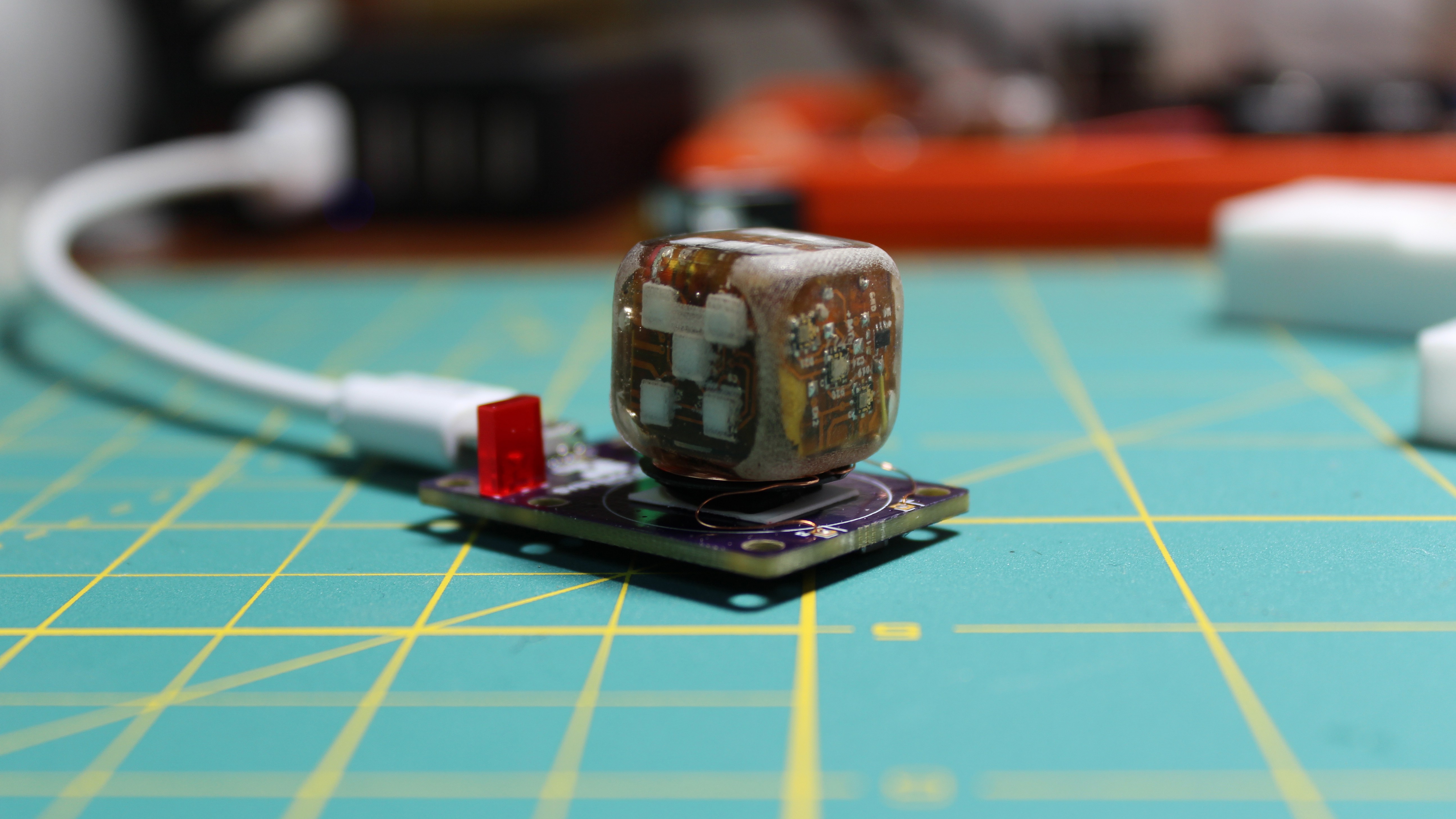
Epoxy
The very last step in assembling the dice, is to pot the entire thing in epoxy! This is a very simple thing, but it makes an enormous difference. I’m pretty pleased with the idea! Potting everything in epoxy serves many purposes at once. First, it keeps me from having to use fasteners to hold everything together. Then it makes sure that nothing moves around, which is a pretty big deal considering how fragile the flexible pcb. But that also gives the dice a really, really solid feel.
 And that is probably the most underrated feature of this prototype. When you hold it in your hand, you can’t tell that it’s full of electronics, it just feel like a regular dice. You can even hear it when I roll it. The previous prototype sounds all rattle-y, whereas this new one sounds correct.
The third purpose of potting everything in epoxy is that it evens out the density, and makes the dice much more balanced. Of course, the density of epoxy isn’t exactly the same as the density of a lipo battery, or the pcb or the components, but it is much much closer to those than air. And so, by filling in all the gaps, the difference in density really decreases.
In fact, I haven’t done it yet, but I’m pretty sure I can make up the last remaining delta by adding a bit of lead here and there inside the case before filling it. And the best part is that because the dice can record every single throw, I can collect accurate statistics on how unbalanced it is and correct for it in the next prototype!
Voila!
But there you have it, that’s how the dice is put together! And while there are clearly still a lot of issues with it, I’m pretty pleased with the result.
Discussions
Become a Hackaday.io Member
Create an account to leave a comment. Already have an account? Log In.
What a cool project! FYI the APA102 is not unusual in being able to be powered through the data lines, most chips do it: https://www.youtube.com/watch?v=2yFh7Vv0Paw
Are you sure? yes | no
This is insane, really great work!
I wonder if instead of inductive charger (which is very cool of course) it wouldn't be more practical to simply have contacts in two of the dice's eyes.
Are you sure? yes | no
Thanks! Honestly I might have to consider that instead, because yeah, inductive charging adds a lot of components, especially considering I essentially have to include a charger with every set of dice that I might want to distribute...
Are you sure? yes | no
Wow, just wow. This is so incredibly awesome and well done, congrats on getting it to work, Jean! This really is one of the most impressive projects on Hackaday.io I've seen.
You've probably thought way better about this but would 6 'normal' rigid PCBs with a very thin substrate and solder connections on the corners work for solving the cracking you get when folding the flex pcb?
Are you sure? yes | no
Thank you so much! I have actually, but I think in the long run (i.e. once I *do* solve the issue, and I'm pretty sure I will eventually) it is more cost effective and easier to assemble to use the flex pcb, especially once I start creating a D12, D20, etc... (because of course I want to! ;) )
Then there is also Rigid-flex, but that's really expensive.
Are you sure? yes | no
That's fair, the flex pcb is great when the problems are worked out. Again great work and thanks for the extensive update, I enjoyed reading it.
Are you sure? yes | no