 Jean Simonet
Hello again friends! It's finally time for an update on the Electronic dice. I just returned from showing the latest version at Gen Con, and it was fantastic! So, what's new?
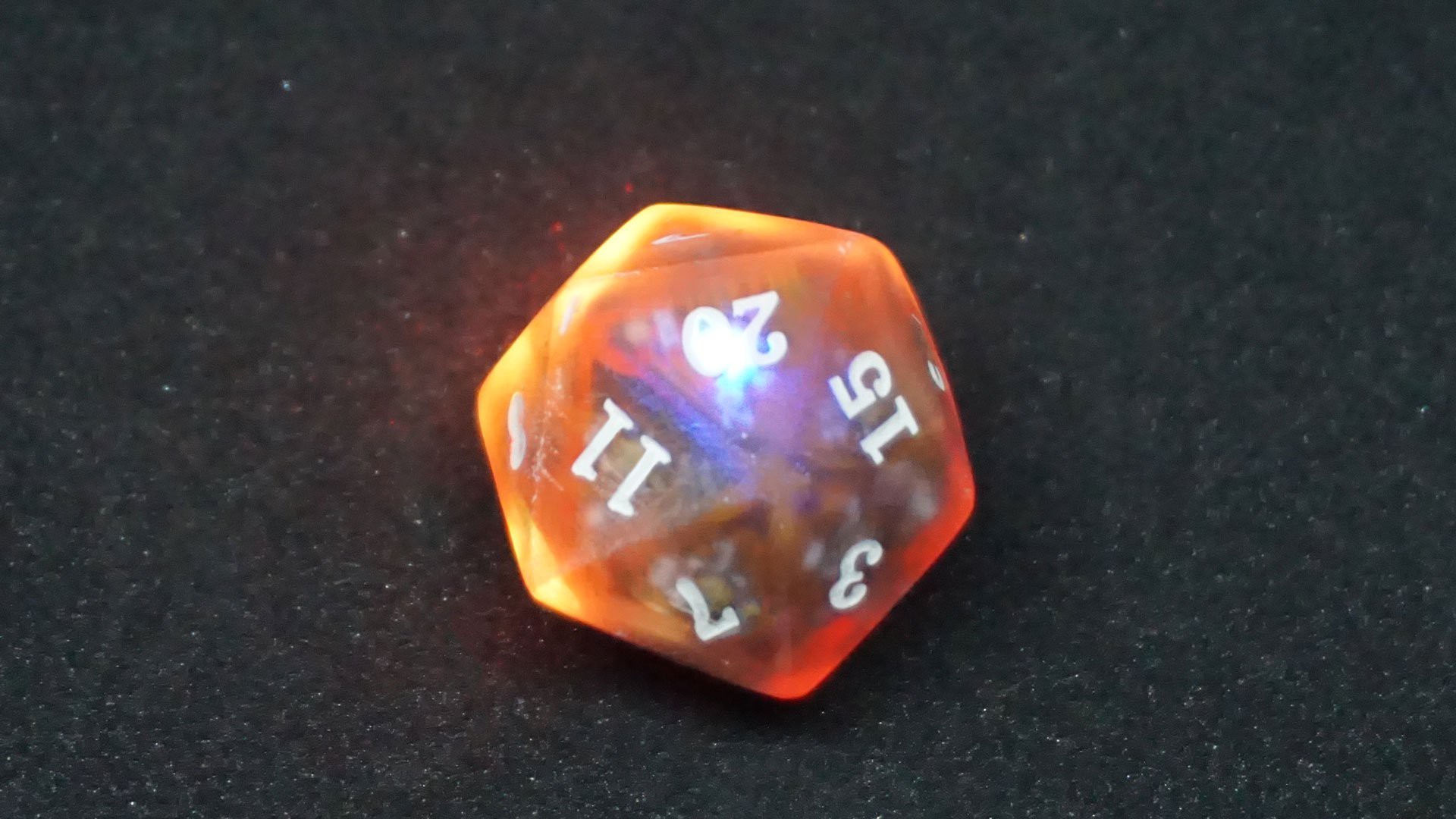
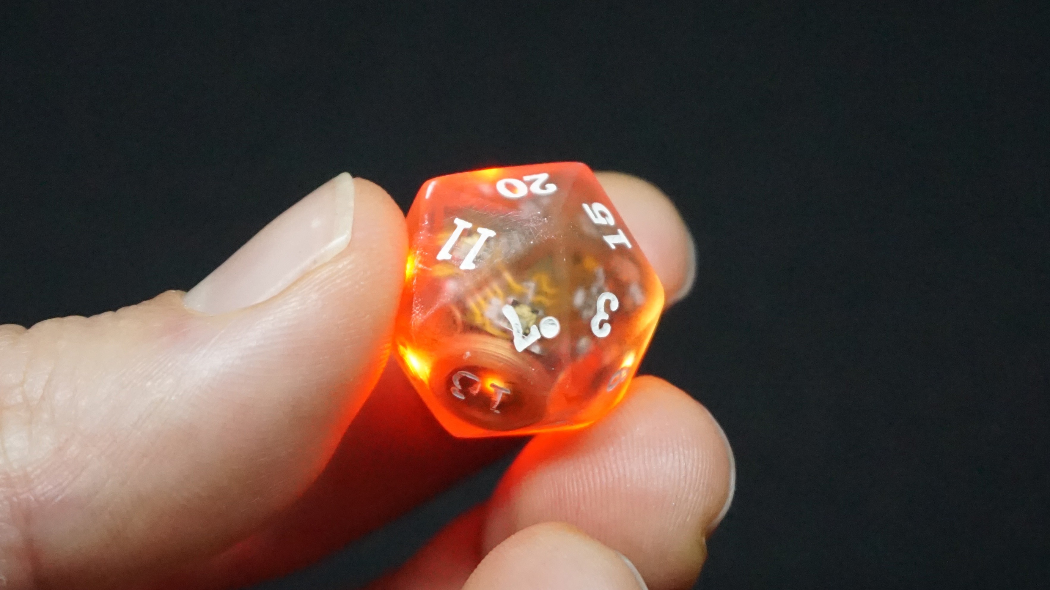
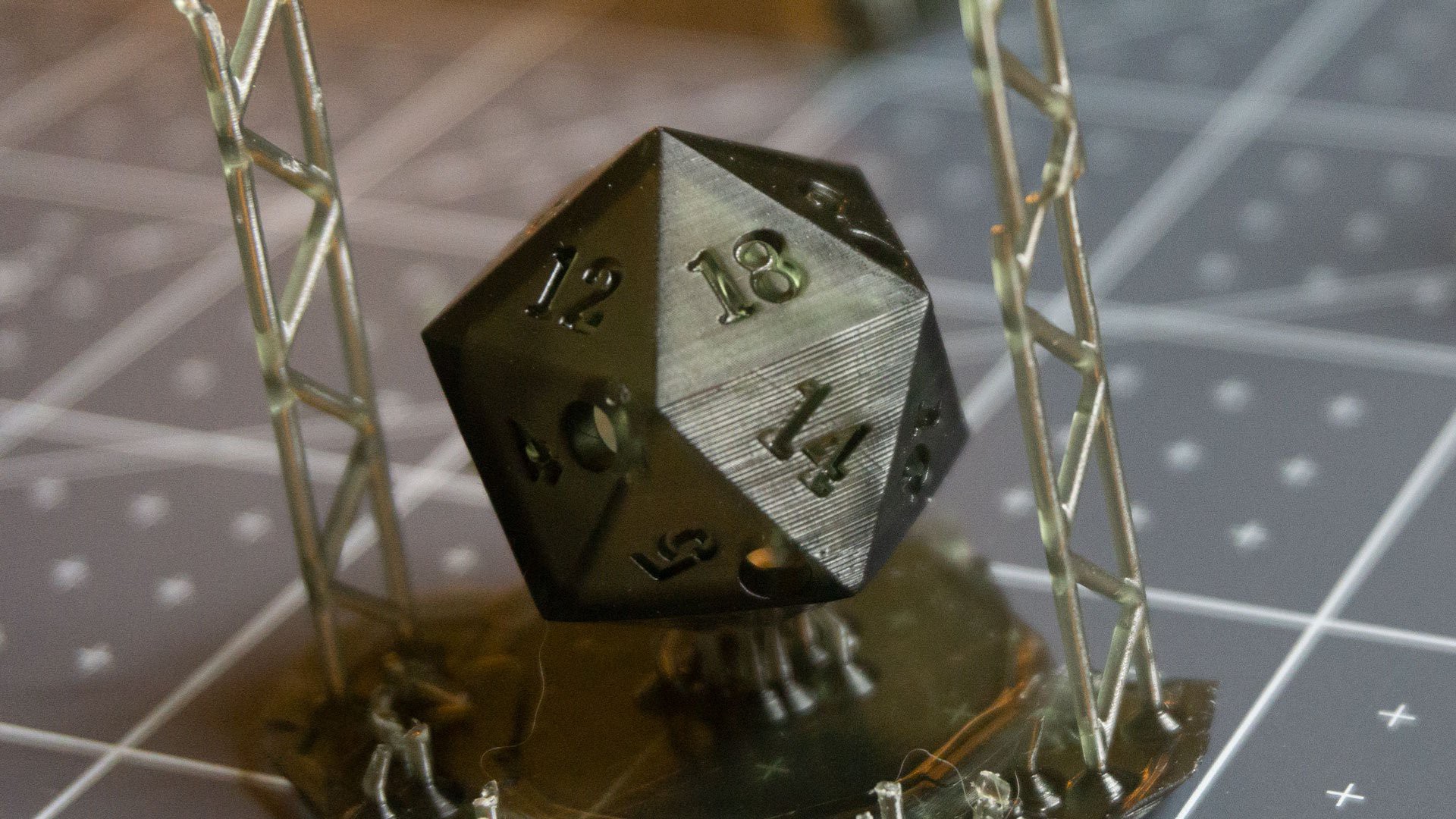
Well, first and foremost, the new prototype is of a D20! Still regular size, still full of LEDs, still inductively charged, and still awesome. In fact, I think the D20 is by far the most fun light up die. There are, however, several other differences with previous prototypes.
New board
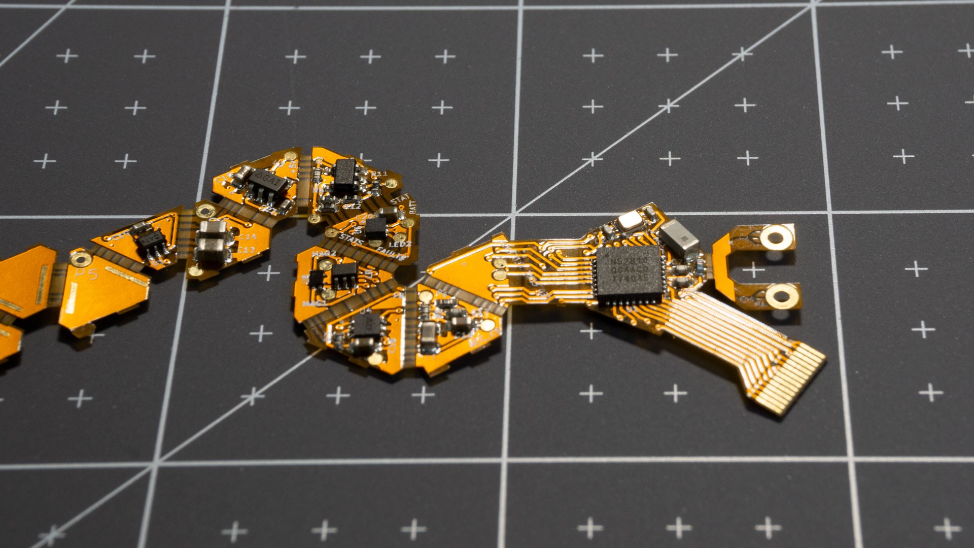
Because this die is 20-sided, the pcb had to be different, and while the volume of a 20-sided die is greater than that of a 6-sided die, each individual face is smaller. That made designing the PCB quite a challenge. Who am I kidding, I loved it! Figuring out how to fit everything in was delightfully painful :)

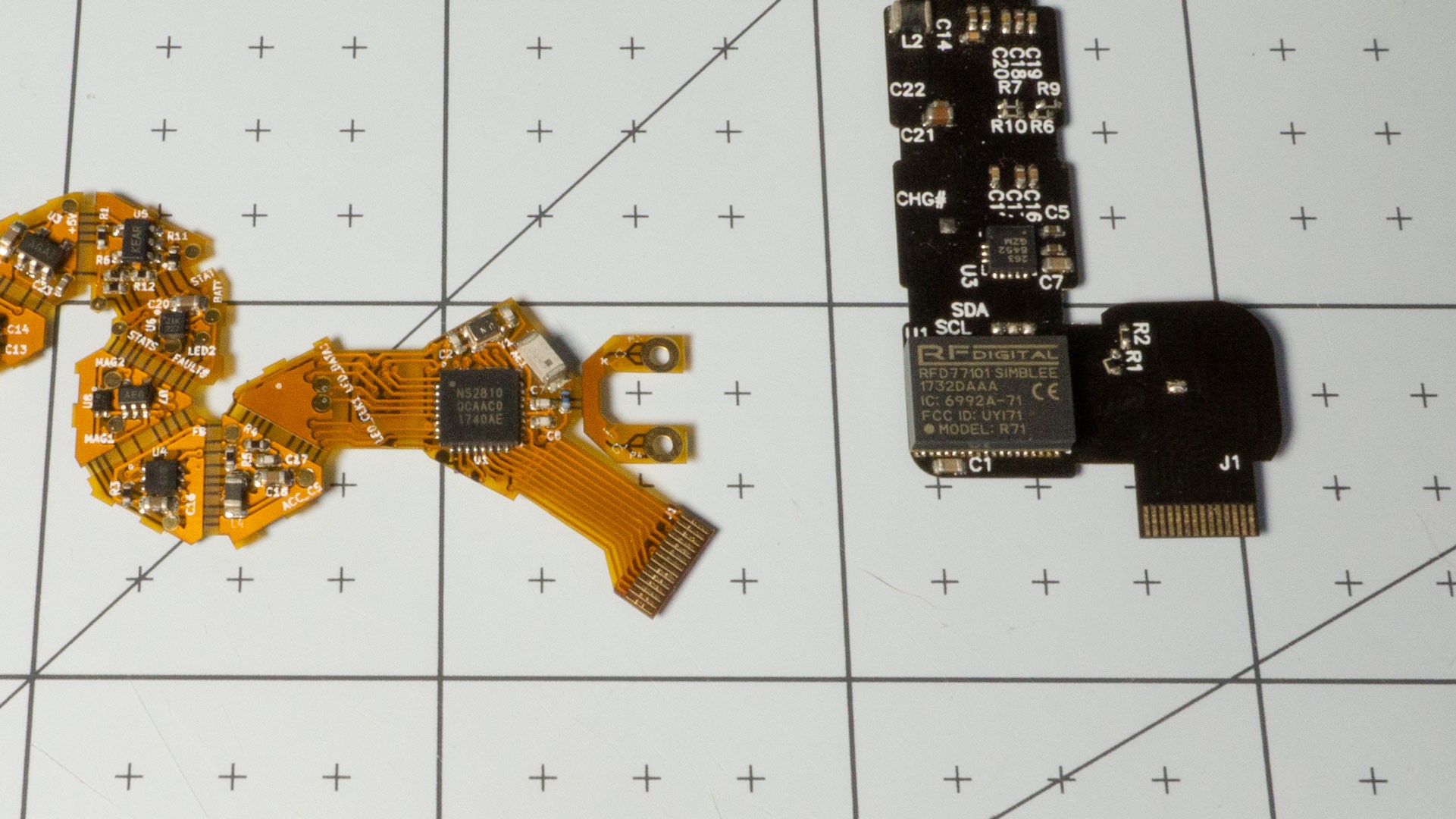
The PCB is an unfolded icosahedron with a couple extra bits. Each face has an LED on the side facing the outside, and possibly some components on the inside. This is still a 2-layer board.
New Chipset
This version of the dice revolves around a nrf52810 from Nordic. The previous version centered around a Simblee module, and while that was incredibly useful to get things up and running (with its arduino-compatible toolchain), the module itself was way, way too expensive. The best deal I could get for small quantities was about $16. The economies of scale couldn't bring that down far enough to make the dice remotely affordable. The Nordic chip, on the other hand, only costs $2.50 in small quantities. Adding a crystal and chip antenna to actually compare apples to apples only brings that cost to roughly $3. That is an enormous difference.
Of course, changing the main microcontroller / toolchain / SDK means that most of the firmware code had to be rewritten, which was a bit of a pain. On the other hand, it also means that I now have control over things I couldn't before, such as the bootloader or even customize the bluetooth advertising packets.
The Nordic SDK is full-featured and the developer community is very active, which means that getting answers to questions is a lot easier. RFDuino, on the other hand, has basically fallen off the face of the internet since they got acquired...
The new microcontroller is also faster than the Simblee module. Simblee internally used an nrf51, the previous generation compared to the nrf52. That is great because it means the firmware can do more work to properly identify dice roll state.
Along the same cost-reducing vein, the accelerometer is also cheaper (new part# VS old part#). It isn't quite as precise (10-bit vs 12-bit), but it is plenty good enough for this application.
New charging circuitry
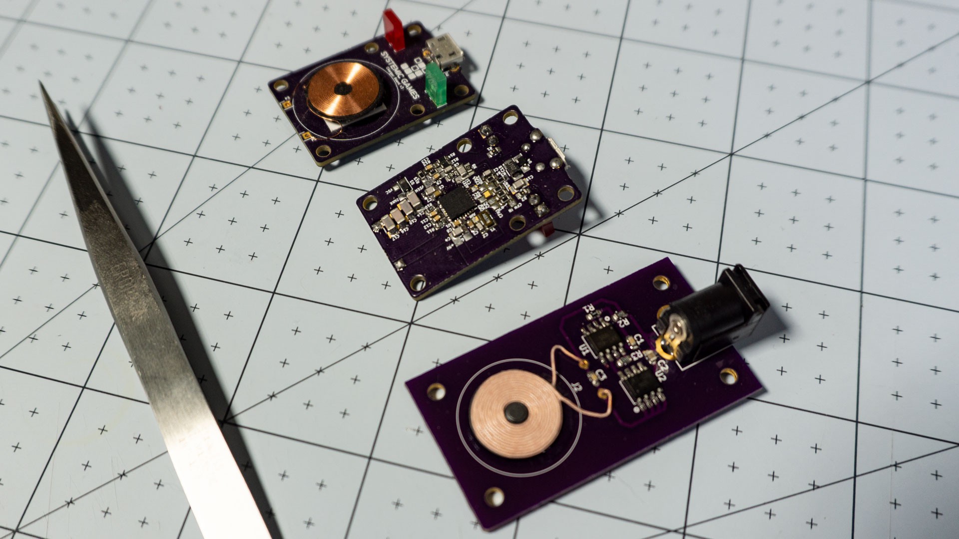
Another big change to the design is the charging circuitry. With the previous iteration, I went with a standard Qi charger chipset. That turned out to be more trouble (and cost) than it was worth. The thing is, Qi chargers are really, really smart. The Qi receiver (inside the die) samples the current being received by the coil and sends that information over to the transmitter (inside the charger) through some clever load modulation. The charger then compares that value against the amount of power it is transmitting, and if the ratio (i.e. efficiency) falls under a certain value, stops the charge and tells the user that something is wrong. When you're trying to transmit several Watts of power at a time to fast charge your phone, this is a great feature, and prevents wasting energy. Unfortunately, because of the physical constraints of the dice design, my power transfer efficiency is pretty low. The coils are really small, and *relatively-speaking*, a lot further apart from each other than the coil in a phone charger is from the coil inside the phone. This caused me a lot of headache, when I didn't really care about wasting at most 100mW of power (for reference, the battery inside the die charges at between 20mA and 40mA).
So instead of that, I went with a dumb charger set up. On the receiver side, I used a <clears throat> FULL BRIDGE RECTIFIER, a couple caps and a linear regulator to create a stable 5V supply from the coil input. Then I added a standard single-cell LiPo charger. I didn't even add any circuitry to decouple the logic supply from the charger's output as the load bias is pretty negligible as long as LEDs aren't lighting up! :)
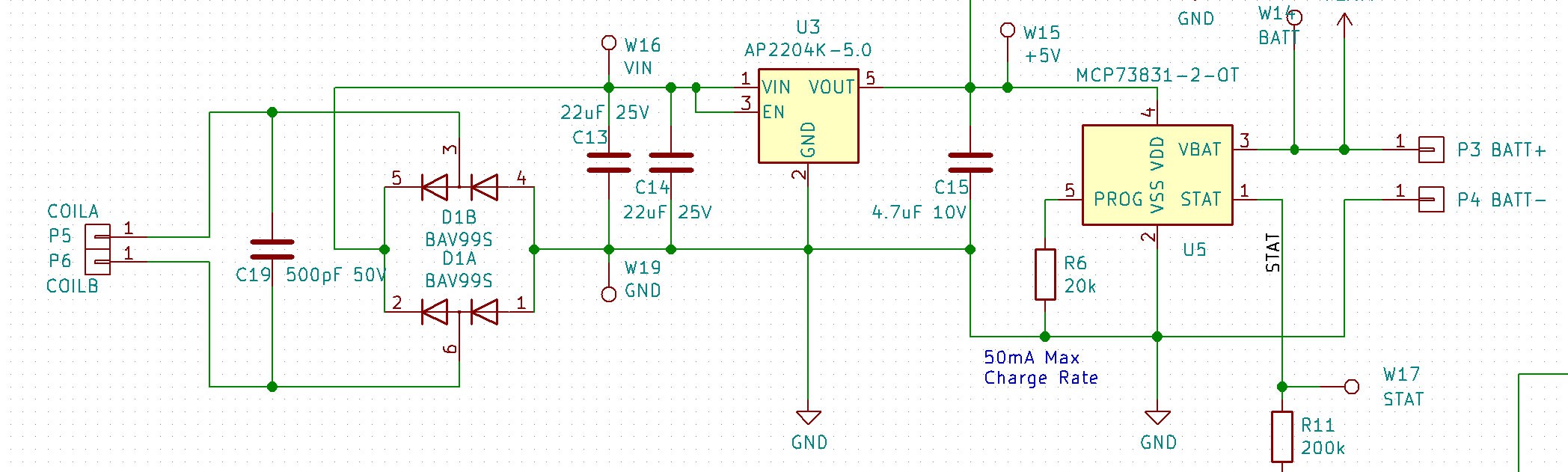
This, of course, also had the side effect of reducing the cost quite a bit. Roughly speaking, the rectifier + LDO + LiPo charger combo came in at $0.15 + $0.10 + $0.50 = $0.75 compared to $3.00 for the Qi receiver/charger chip (BQ51050B).
And that's not even the full story. The Bill of Materials for a Qi charger is quite large, in fact, the cheapest single-chip Qi transmitter (NXQ1TXH5) is another $3.00 or so. Compare that to the alternative, some cheap wireless charger chips off Alibaba (XKT-335 and XKT-412) for $0.15 a piece and you can imagine the overall savings. And since it seems likely that - on average - I'll need to provide a charger for each die, it's kind of like adding the cost to the die directly.
So obviously the lesson here is that being really smart isn't always a good thing. ;)
Excluding the LEDs, the parts come out to about $5.50 per die (for a D20, it's about $7.50) if I were to make 1000 dice. Of course that doesn't include any of the assembly / manufacturing costs, which is why I've been telling everyone that my target price will be between $25 and $30 per die.
Resin Casting
It's really strange how sometimes you get so accustomed to something that you simply forget that things can be different. I think this is something most of us know, have seen or have been told about before, but it is really something you don't fully appreciate until it has happened to you! Sorry, I know this sounds very philosophical, but in this case I'm thinking specifically about an assumption I've made about the dice from very early on. That assumption was that the way to create the dice was to put the electronics inside a plastic shell in the shape of a die. In fact, the first design I uploaded on Hackaday.io featured a removable lid, so that you could replace the battery. Along the way, I figured out how to fit a rechargeable battery instead, and even an inductive charging coil. I was super happy with that upgrade, because it meant that I could try to pot the entire insides of the dice shell, battery, electronics and all, in resin, and make the dice that much more solid (and great feeling).
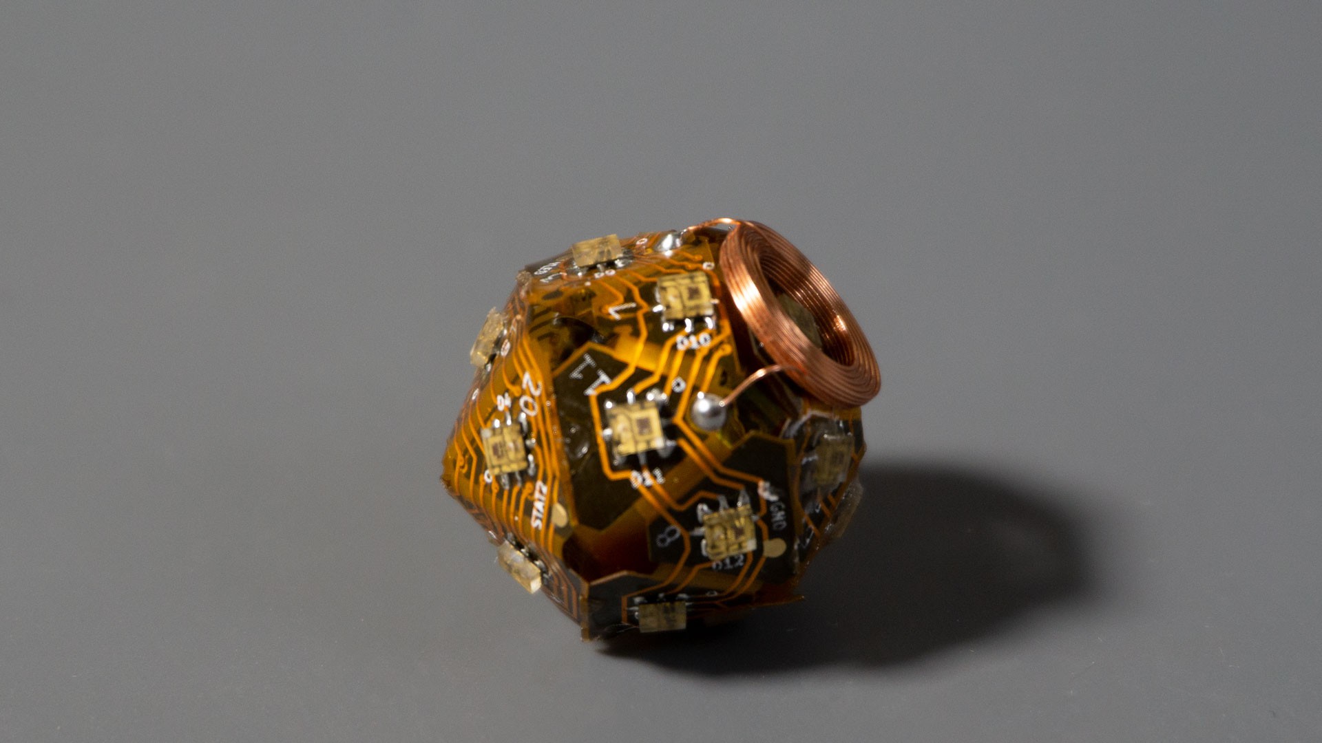
But it took me MONTHS to realize that I didn't need the shell at all anymore. I had been agonizing over how to design those such that they could be injection molded (and dealing with the draft angles, overhangs, etc...), and didn't even think for the longest time that, well, I don't need a shell at all! I could simply place the folded-up electronics inside a dice mold, and cast the whole thing just the way you would a regular resin die. It's one of those things that really make you go "Doh!!!".
So, yeah, the dice are now directly cast in resin. This, of course, brought a few issues of its own, but overall it was a massive simplification to the assembly process.
The first difficulty was simply me learning the ins and outs of mold making and resin casting. In the end, my process went like this:
- 3D-print positives
- Cast Silicone molds from positives
- Cast resin dice from Silicone molds
If you're interested in more details, there are tons of resources on Youtube. I followed all of them, got a vacuum chamber (for the Silicone) and a pressure pot (for the resin) and things mostly came out good.
I did have one thing that really tripped me up, which was mold release: make sure you use the correct mold release!
There are two kinds: Silicone-based sprays and Oil-based sprays. Do NOT use Silicone-based sprays when you are creating the molds (Step 2 above). Otherwise what will happen is that the silicone in the spray will flow into all the micro features of your positive (and if that positive was 3D-printed it will have lots of them) and then proceed to cure along with the silicone that you're using to create the mold. The end result is the complete opposite of what you expected in the first place: you won't be able to remove the mold from your positive...
For the resin casting, you can use either sprays, or none really...

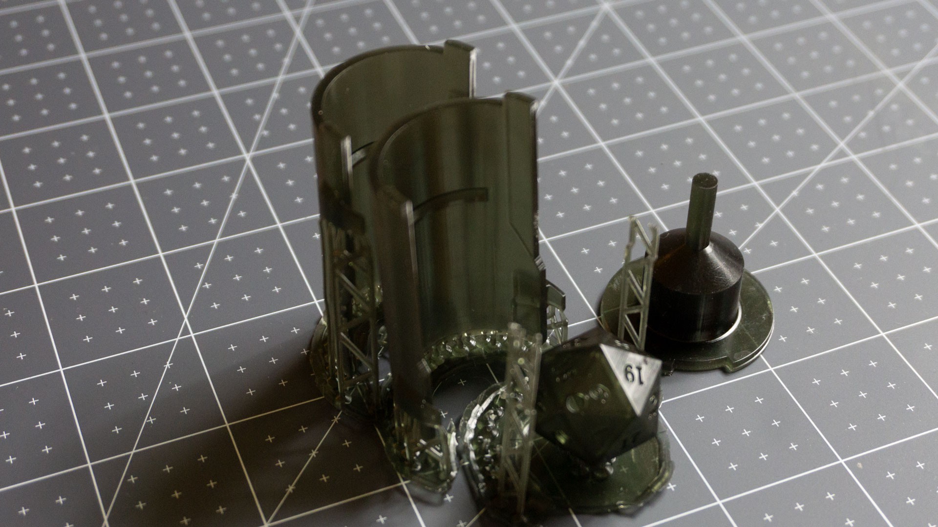
Anyway, casting the dice ended up needing to be a two-step process. The reason for that was to make sure the electronics and battery would stay in the middle of the die, and not float up, sink down or drift. The idea is that the first casting can register with the circuit board / LEDs, yet have portions that stick out and can themselves register with the second mold (i.e. final die shape). In other words, I start by making a solid 'puck' out of the electronics, and then fit that puck inside the final mold.
This process worked well enough to create a few dice for me to show off, but it isn't great yet. Even though the puck kept everything centered nicely, it could still be placed inside the final mold incorrectly, causing some misalignment between the LEDs and the faces. I am investigating a different registration method that does require a bit of sanding afterwards, but that sanding is already necessary cut cut off the sprues left over from the casting process.
The jury is still out on how this process will affect manufacturing costs. Injection molding plastic shells is really cheap, cheaper than resin casting, but with the previous design I would still have needed someone to fill the shells with resin and then fit the top cover. All that while making sure there were no air bubbles - a difficult task. Here I need someone to do two resin castings / cleanup per die. It seems like more work, but it's fairly commonly done already. Obviously I need to get some quotes.
Discussions
Become a Hackaday.io Member
Create an account to leave a comment. Already have an account? Log In.