 jurc192
The goal is to make LEDs glow and have some sort of candle/fire effect (brightness varying a little, slowly). And they should only turn on at night- which means there will be somekind of light sensor.
It has to be simple, cheap and it should run on (few?) coin batteries. I'll be happy if it lasts more than one day. And it has to look cute.


")


")


 Sam Ettinger
 Yann Guidon / YGDES
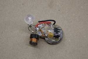
 Elliot Williams
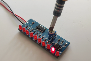
Neat! They sell LEDs that flicker randomly like a candle on Ebay and Aliexpress. Just make sure you talk to the seller so you get the right LED, because most Chinese sellers confuse "blinking" with "random flickering".