 Andy Smith
AC-DC Power Supply
I anticipate the biggest space-eater on the board to be the power supply. Now, I am by no means an electrical engineer and I have never designed a board that interfaces with 230V AC before, so to do this safely I looked for the most self-contained solution I could find.
That's when I stumbled across the HLK-PM01 (datasheet) and a series of very useful blog posts about how to implement it safely. The part takes a 230V AC input and supplies 5V DC up to 600mA, with minimal extra parts. It's a fairly bulky component, but at 34x24mm and 15mm height, it will just about fit in the bottom recess under the board with just under 2mm to spare.
As recommended by Skippy's blog posts, I'm going to add a varistor and fuse to the AC input. On the output side, hopefully a pair of 0.1uF and 10uF smoothing capacitors will provide a clean enough output to the low voltage side.
There are some concerns with emissions, but as I'm not developing this into an actual product, I'm not going to worry too much about this. I may revisit this if there are any wireless performance issues with the ESP8266.
Final note on this: it's a 5V power supply and the ESP8266 is a 3.3V board, but having both 5V and 3.3V available (via a linear regulator) on the board will give me more options later for part selection.
Relay
This one required a bit of searching to find something low-profile enough to fit where the housing tapers off to 13mm underneath the board in the middle. A common, cheap part that I was planning to use (the GHI SRD-05VDC-SL-C) has a height of 15mm.
I found the Omron G5CA-1A, a 10A @ 250VAC rated relay clocking in at a svelte 11mm height. This is also a normally open contact without a normally closed terminal, which should make the high current traces on the board easier to route (the common contact pin on the SRD-05VDC is nestled in between the two coil pins).
Sketch
With the two largest components in place, I started doing some accurate measurements on the board and began the CAD layout.
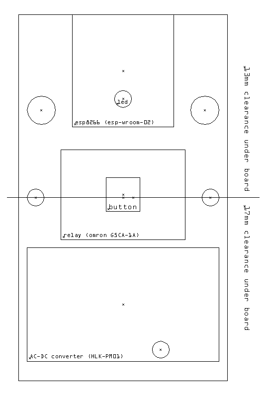
On here I have marked the 4 holes on the board, the support standoff (currently under the power supply - this will have to go!), and the point where the space in the housing drops from 17mm to 13mm.
There are two components that will need to go in the same position on the board - the button and the LED - in order to match up with the outer casing. I was planning to use the same through-hole components for both, but as I'm mounting components under the board I will need to re-think this.
I found a suitable surface mount button that crucially has the same height as the through-hole component on the original board. (4.3mm)
The LED was a bit of a problem. The original board uses a 3mm through-hole LED that extends 10mm from the top of the board and pokes through the top casing. I considered placing some surface-mount pads and using the same part (bending the legs), but had a better idea. I'm going to use some 3mm acrylic rod to create a light pipe down to the board, and use a surface mount RGB LED. Having an RGB LED will allow for different status messages (e.g. indicators for switch on/off, failure to connect to WiFI etc).
I'll use a WS2812B for the LED. It will allow for control from a single microcontroller pin, and reduce additional passive components required (current limiting resistors) and traces on the board.
Microcontroller
I was planning to use the very common and very cheap ESP-12E module, but it's a few mm too long to fit on the board. I'm instead opting for the ESP-WROOM-02, a slightly smaller module. It doesn't have as many GPIO pins broken out as the ESP-12E, but that's not really a concern for this project. It's not quite as cheap and widely available, but I've found them for $2.70 a piece on Aliexpress.
In the next update I'll begin the PCB schematic in Eagle.
Discussions
Become a Hackaday.io Member
Create an account to leave a comment. Already have an account? Log In.