 Quinn
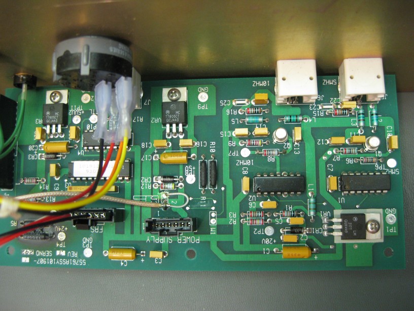
QuinnStarting with the EFRATOM PRFS-102 module, it is a pretty basic case, likely a generic one and put together by EFRATOM. The front panel has isolated BNC connectors for sinusoidal 10Mhz and 5Mhz outputs, and a TTL output with selectable frequency. A rotory switch selects between 1, 5 and 10Mhz. When plugged in, the power LED does not come on, but after warmup, the Rubidium Lock LED does turn on. The outputs have no signal.
The lid removes simply to show a basic construction with an off the shelf cage power supply, the Rubidium module, and a circuit board attached to the front panel.
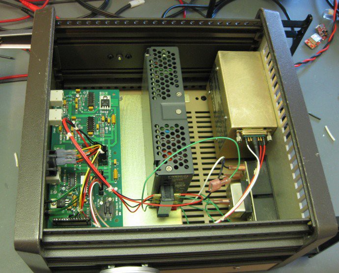
The power supply is 24VDC, and tests good. Pulling off the front panel to access the circuit board I could get a good look, and immediately find a problem.
The PCB is very much burned under a pair of resistors:
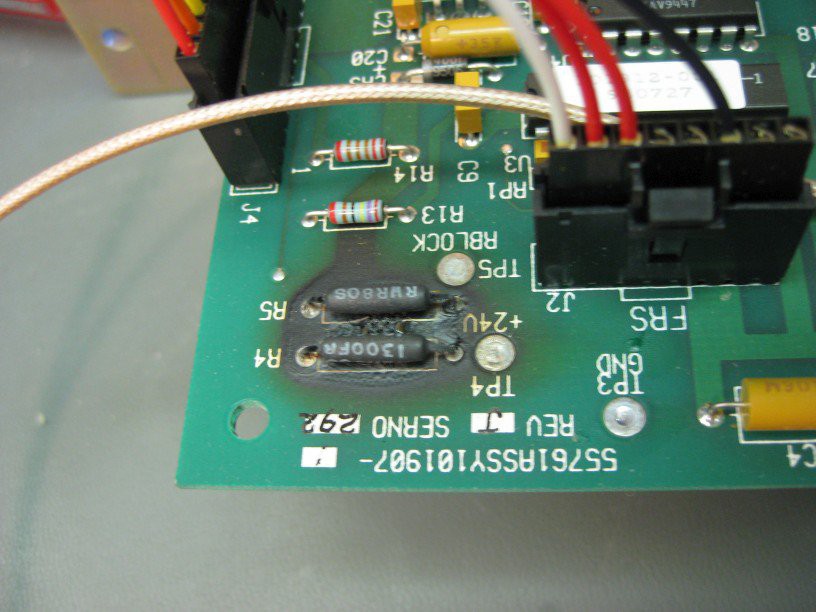
As it's a uncommon resistor, it is labeled with a full part number RWR8031300FR which reveals them to each by high reliability 2W 130ohm 1% resistors. Measuring across them shows open circuit. There are another pair in on the PCB which appear to be used in a similar way, and as they are wired in parallel, do measure 65ohm.
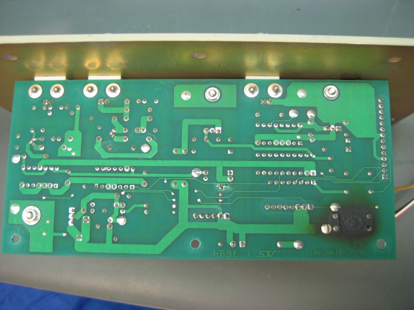
The traces show that the 24VDC from the power supply come onto this board, and in addition to local circuitry also go to a connector which powers the Rubidium module. This explains why some of the board logic does not operate, while the module does.
Discussions
Become a Hackaday.io Member
Create an account to leave a comment. Already have an account? Log In.