 Quinn
QuinnPowering the unit up again, and after waiting for the reference to lock, I used an external supply to apply 8V to the input of the 7805, after the series resistors. Measuring the output showed 5V, and the 10Mhz now comes out the TTL output, so it seems like repair will only take replacing the resistors.
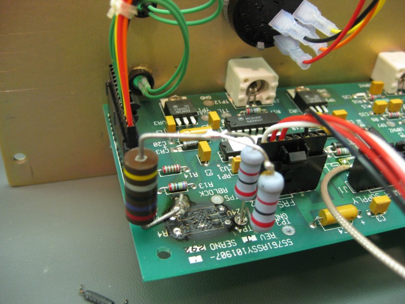
My stock of power resistors is limited, and I didn't have any 130 or 33, or similar values I could use to make up the 65 result. I did have some other values, and decided to parallel two 82 ohms, and add that in series with a 26. Thus results in 67, very close to the original. The slightly larger resistance will slightly reduce the current drive that is possible, but still will net almost 0.254A while maintaining voltage spec, and up to 0.33A at short circuit. Calculating the power in each resistor results in a larger margin than the original solution.
I bodged them in, standing up off the board so that if they ever overheat, they won't burn the board.
Testing, this worked. After putting it all back together, I tested further. The outputs are all stable. 10Mhz sine output is clean, with 4.2Vpp(centered around 0) into 1Mohm, and 3.0Vpp in 50ohm, as expected. The 10Mhz TTL output is clean with edges between 0.18 and 4V. (50ohm terminated with coax connection to scope, or in 10Mohm via probe)
On to the next one then!
Discussions
Become a Hackaday.io Member
Create an account to leave a comment. Already have an account? Log In.