 Ted Yapo
Astute readers will have noticed I incorrectly said I needed a boost converter to transfer energy from the 3V coin cell to the 14V capacitor bank.

This is true once the capacitors are charged above the cell voltage, but from 0 to 3V or so, I need a buck converter. Unfortunately, I can't just connect the coin cell directly to the capacitors to get them initially to 3V. If I did that, the internal resistance of the cell would waste too much power - to get the maximum energy from the cell, it has to be transferred slowly, probably over the course of many hours. So, I need a buck/boost converter.
Since I don't really care that the cell and the car share a common ground, I can use the simplest buck/boost topology, which incidentally inverts the output voltage. The car won't mind as long as I get the polarities right at the battery connection. I made a first pass at a LTspice simulation for the converter, as shown above. I chose a P-channel MOSFET from the library basically at random; none of the components are set in stone yet. R1 simulates the internal resistance of the CR2477 cell - this changes over the life of the cell, so I'll have to account for that at some point. C1 serves to smooth the current drain from the cell, providing a reservoir for the current pulses into L1. M1 switches current into the inductor when turned on, then switches off to allow L1 to drain into D1 and C2, the B.F.C. (note the "67" with no units - that's 67 Farads).
Here is what the cell current and output capacitor voltage look like in the first 100ms of simulation:
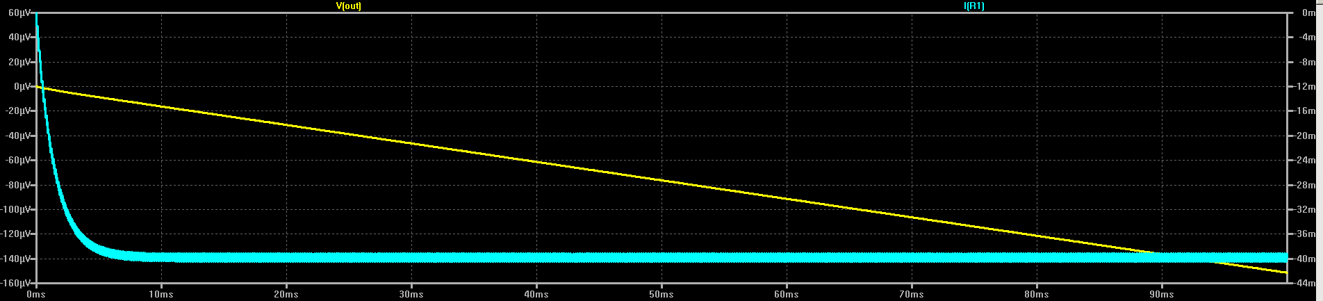
The circuit draws about 40mA from the cell, which would deplete the cell in roughly 25 hours - I may have to wait a day for the capacitors to charge, but this should extract a decent amount of the available energy from the cell. Once I have a stock of cells to play with, I can look into decreasing the charge time (or possibly extending it, if necessary).
During these 100ms, the capacitor voltage has risen to around 150 uV. Not very impressive, is it? But, if that rate were continued, it would charge the capacitor to 150e-6 * 10 * 60 * 60 * 25 = 135V in 25 hours. Of course, this would greatly exceed the capacity of the cell, so can't happen. In reality, the output of the converter will be roughly constant power, causing the dV/dt on the capacitor to decrease over time. So, the last 100ms of charging will actually see much less than 150 uV of voltage change.
Oh, the magic pulse source, V2, driving the MOSFET is probably a PIC15LF71. In the simplest case, it can just generate a constant driving waveform, but if there's something to be gained, I can monitor the cell and/or capacitor voltages with the PIC ADC and make adjustments. I haven't really thought that part through, yet.
Discussions
Become a Hackaday.io Member
Create an account to leave a comment. Already have an account? Log In.