 Kyle Gabriel
March 28, 2012
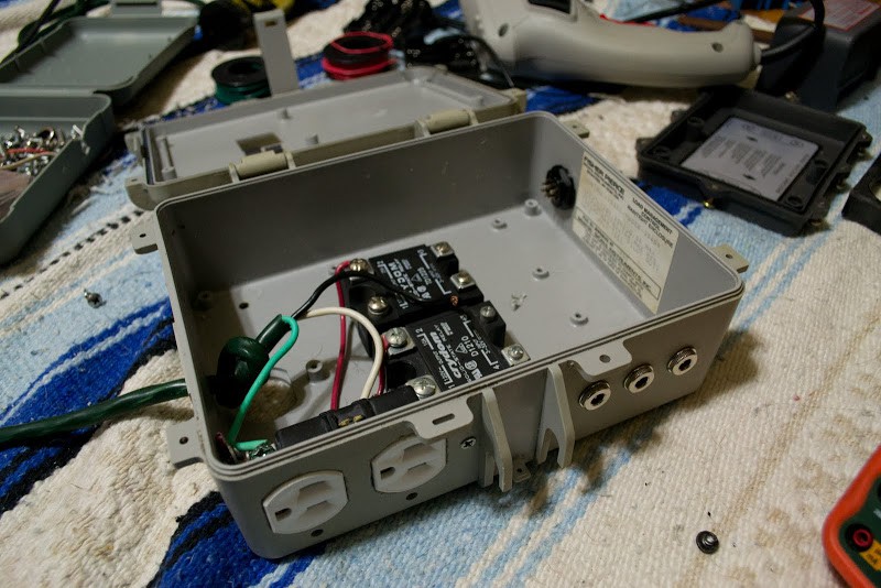
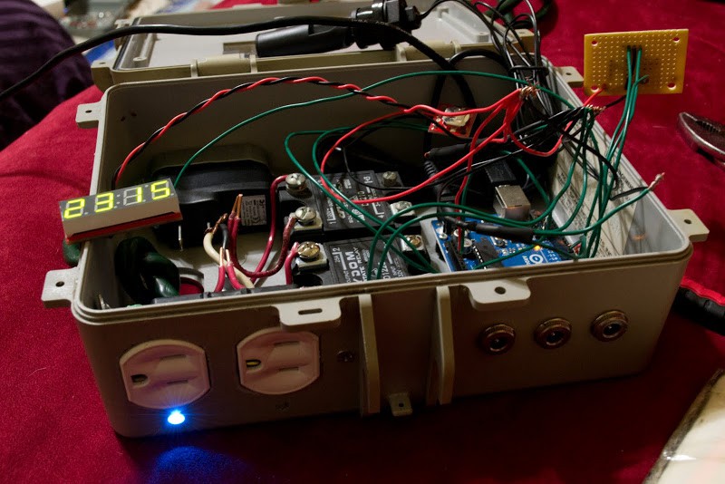
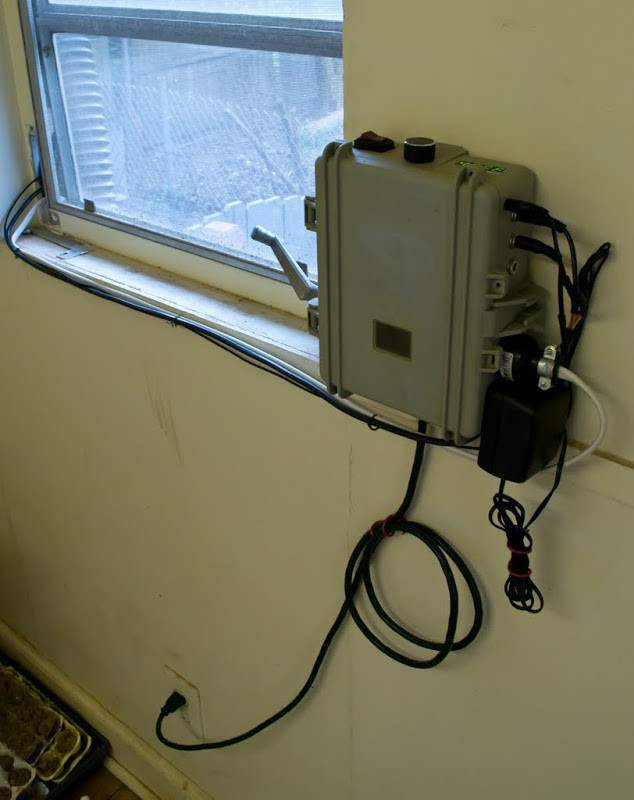
The design I settled on is comprised of three barrel plugs and a single 3-lead audio plug (float sensor, pump pressure switch sensor, temperature sensor, and rain sensor), two solid state relay-controlled electrical outlets (pump and 24v valve), and a blue LED next to each outlet to signal the outlet is live.
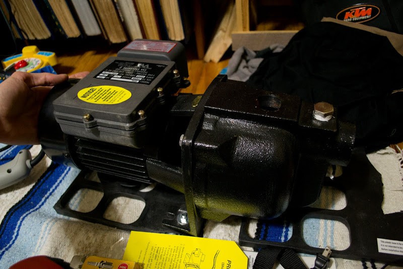
This is the 1/2 HP well pump I'll be using to transport my water from the tanks to my sprinkler head(s). The rated output is 9 GPM (gallons per minute) @ 30 or 55 PSI (pounds per square inch), and has a current rating of 8.5 amps. At 120 volts, that's 1020 watts of power consumption. If we assume my area's January 2012 electricity cost of $0.113/kWh (killowatt-hour) is the yearly average, it can be projected how much it would cost to water every day of an 8-month growing season, for 1 minute per day.
60 seconds/day x 30 days/month x 8 months/year x 1 minute/60 seconds x 1 hour/60 minutes = 4 hours
4 hours x 1020 Watts = 4.08 kWh
4.08 kWh x $0.113/kWh = $0.46
The basic operation will turn the well pump on at scheduled times. If the rain barrels begin to run low on water, the float sensor will signal the sprinkler valve to open at the house's spigot. This valve is connected to a barrel and prevents the water level from falling below the pump's intake pipe. A temperature sensor prevents the pump and valve from powering if it's too cold (or will soon be too cold) and a rain sensor will be incorporated to prevent watering while or after it's rained.
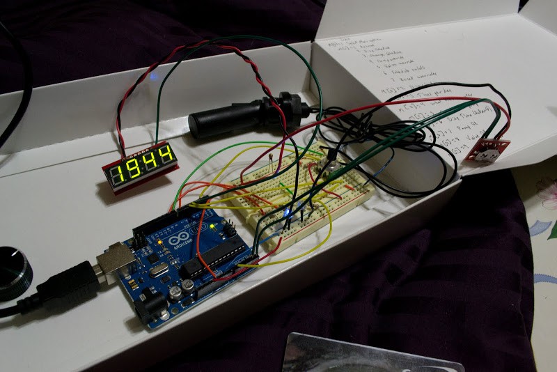
Further progress shows the rotary encoder soldered to its board and the rest of the components plugged in to test before everything is soldered and tucked in. The first test has all components properly detected and operating.

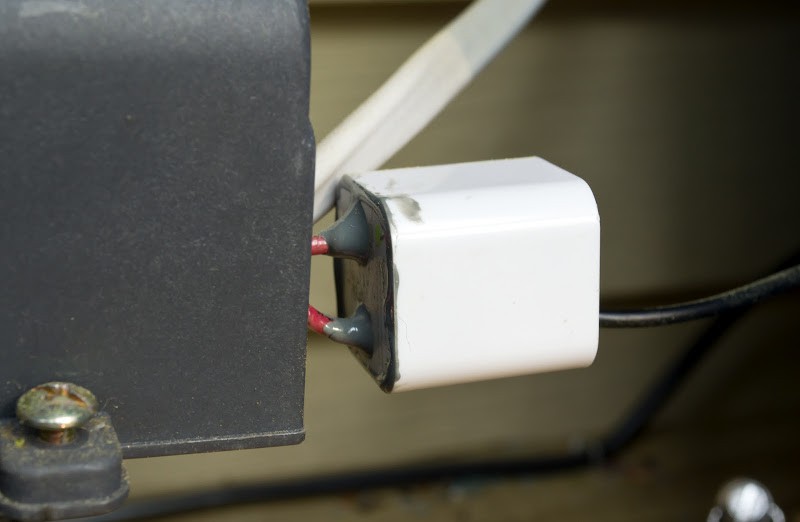
When powered, the pump relies on a pressure switch to enable and disable the current to the motor. In a situation where there is a blockage in the outflow line (debris collecting in the sprinkler, for instance), pressure may build. If the pressure exceeds ~50 psi, the switch will kill the power to the pump. If no pressure tank is installed, the line pressure quickly drops and the switch resumes powering the pump motor. In tests, the off/on cycling occurs rapidly, about 2 to 3 times per second, and if the blockage does not pass the pump may burn out. To prevent this, I used the 5.5v signal from a USB power adapter to signal from the pressure switch that power was continually being given to the pump.

The enclosure was cracked open and wires were soldered to the 120v power leads and from the 5.5v USB leads. The enclosure was resealed with marine epoxy. The finished product can be seen protruding from the pressure switch enclosure, below. A problem appeared while testing, and it was that the charged capacitor within the USB adapter prevented the voltage drop from being detected. This was resolved with a few resistors.
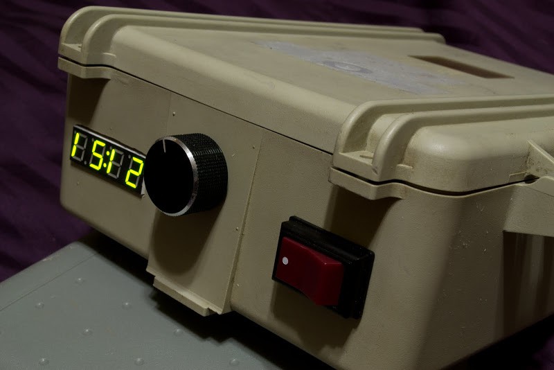
Operation and Navigation
The current time & temperature will alternate on the display by default. If the colon is blinking when the time is displayed, the schedule is on. If the colon is not blinking and stays solid, the schedule is turned off. While the time & temperature is being displayed. The knob can be pressed to activate the control menu. Turn the knob to change a value, then press to confirm the value.
Menu Options
1: Exit the control menu and return to displaying the current time.
2: Display schedule(s) in the format: start time, duration on, days between running, next run day (1=Mon...7=Sun).
3: Change schedule
A: "# x" #: Which schedule, x: How many schedules to use (up to 3).
B: "XXYY" X: Starting hour, Y: Starting minute. Selecting the time will confirm & display the next schedule time.
C: "# x" #: Which schedule, x: watering duration in seconds (~5 gallons/minute).
D: "#d x" #: Which schedule, x: how many days between running the schedule.
E: "#n x" #: Which schedule, x: Which day of the week to start schedule (1=Mon...7=Sun).
4: Override the pump (to run the sprinkler) to either remain OFF or ON
5: Override the valve (to fill the barrels) to either remain OFF or ON
6: Turn the timer schedule OFF or ON
7: Reset the pump and valve overrides so they return to a scheduled operation (if schedule is turned on)
8: Display temperature history over the past 24 hours, 0 is the most current temperature stored
Emergency Modes
If an emergency is detected, the valve and pump will remain off until the button is pressed to resume normal operation. During emergency mode, one of the following will interupt anything currently being displayed:
-E-1: The valve was open > 15 continuous seconds. This indicates the water is not activating the float switch in a timely manner. Ensure the hose going into the tank is connected & clear, the valve is operational, the spigot is open, the tanks are free of leaks, the float switch is free to move, and the switch is indeed activated when the water level reaches the sensor.
-E-2: The pressure switch began rapidly turning on and off or the pump has run dry. This indicates there is too much pressure building in the pump outlet or no water at the pump inlet. Ensure the outflow hose from the pump is not kinked, the sprinkler screen/heads are clean, and there is an adequate amount of water reaching the pump inlet.
-E-3: The float switch has been activated after more than 3 minutes from when the end of a scheduled watering. This indicates there may be a leak or water is being manually removed via the barrel's spigot. If the barrels were allowed to fill, which could take over a minute of the valve turning on and off [to equilibriate the water levels], the float switch should not activate this late. If water is being manually taken out, remember to exit emergency mode in order to resume the schedule.

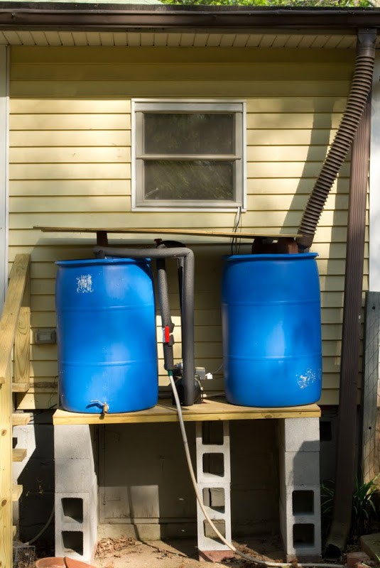
Now that the circuitry is complete, I can focus on the water storage and delivery system. The general idea is that water will enter one 55 gallon barrel by flex tubing from the gutter, a hose connecting the two barrels near the bottom will equilibrate the water levels, and the pump will then pressurize it back above the water line and down to a hose that runs out to a sprinkler in the garden.
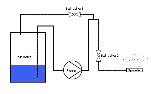
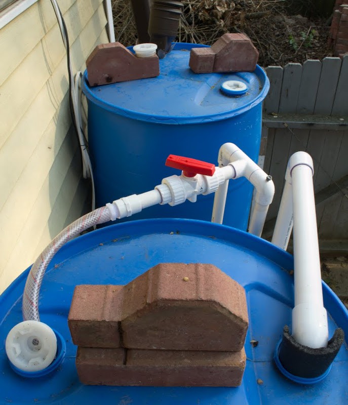
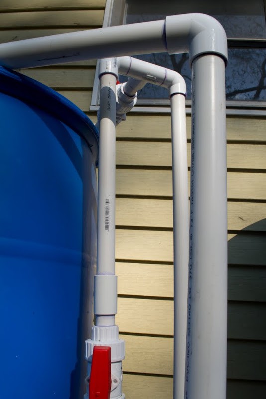

The outflow pipe from the pump rises over the point of the highest possible water line to prevent water from siphoning out while the pump is not running. This is only possible when a separate pipe extends from the top of the bend to allow air to be introduced into this bend immediately proceeding the pump being turned off. This vent serves two purposes: it allows air to flow into the top portion of the pipe when the pump shuts off, preventing continuous water pressure toward the sprinkler (which can slowly drawing all water from all barrels), but it also alters the water pressure that's allowed to reach the sprinkler by either closing (increase pressure) or opening (decrease pressure) Ball-valve 1, diverging the flow back into the barrel so no water is lost. With Ball-valve 2 in-line after the bend, there is now the ability to completely alter the pressure from 0% to ~100% to the sprinkler beyond Ball-valve 2.

A sprinkler valve fills the barrels from the spigot if the water level falls below a minimum level detected by the float sensor.

Float sensor protruding from the barrel.
Temperature sensor encased in epoxy.
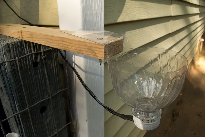
The rain sensor is a recycled plastic water bottle nailed to a board.
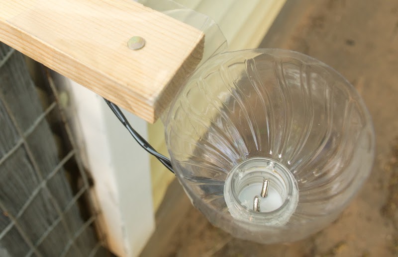
It measures resistance between the screws.
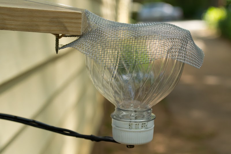
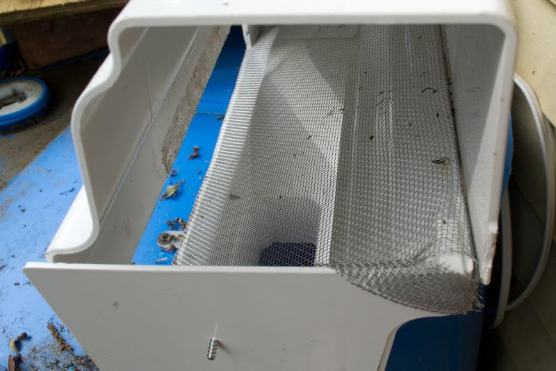
Protection from large debris.
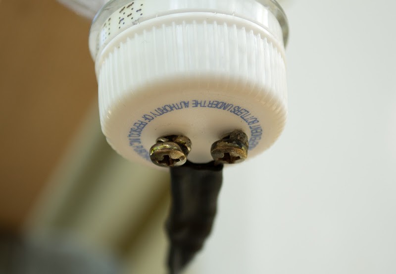
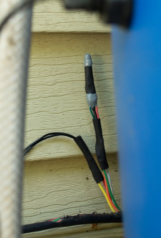
Much heat is required to properly solder stainless steel.
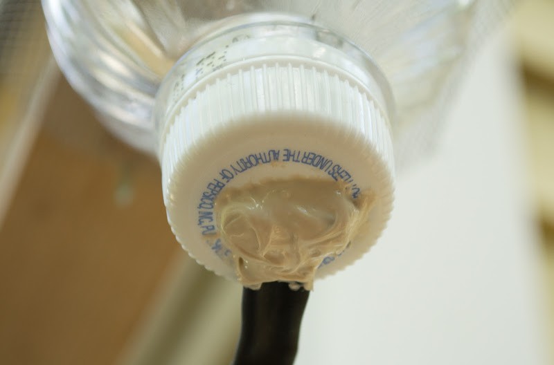
It's best to protect these connections from oxidation/corrosion.
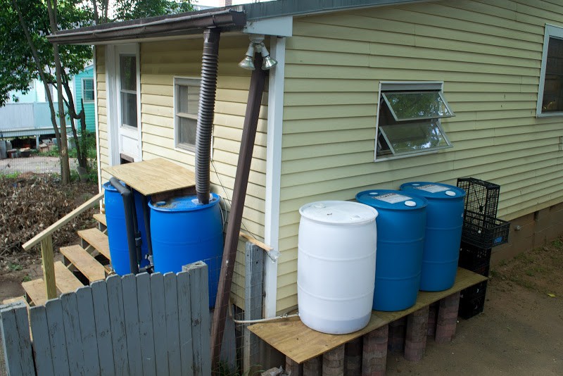
2012.04.29: 3 additional 55gal barrels have been added to the system.

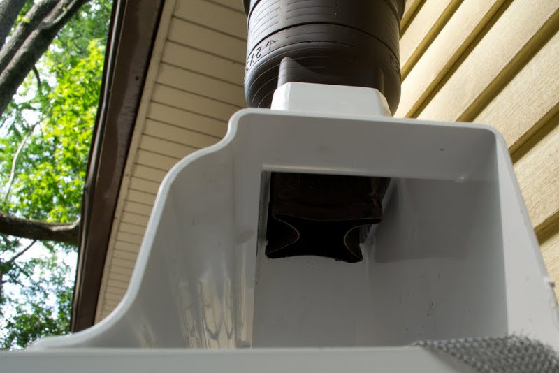
2012.05.11: Self-clearing filtration system added

I hope this has served as entertainment, inspiration, or a practical how-to for your own garden project.