 jaromir.sukuba
In the previous log I touched the surface of capacitor charging problem. I can't connect the battery to capacitor directly from two reasons:
- The battery has high internal resistance, capacitor is discharged at the beginning, thus acting as short circuit, overloading battery.
- If I even had battery with zero internal resistance, the capacitor would charge up to voltage of cell, which is falling slowly. It would stabilize at some equilibrium, cell wouldn't deplete any lower and capacitor wouldn't charge any higher.
If point 2 wouldn't be deal-breaker, the first one would be. Charging the supercap from CR2032 would end up in flat cell battery in hour or two and capacitor charged to tenth of volt or so.
Fortunately, DC/DC converters are here to help. As the voltage during cell depletion is decreasing from 3V to approx. 2V and capacitor voltage is increasing from 0 to 2,7V, simple step down voltage converter will not cut it. In fact, step up is bad too. What I need here is step-up and step-down combination (it can be done using two discrete DC/DC converters, like CR2032->5V and 5V->capacitor), or better using buck-boost coverer that can work in both modes. I took the first picture from aforementioned wikipedia link as basis of my work. It's simplest B-B converter, but with the limitation of negative output voltage. Since I don't care much what is the voltage polarity against cell "ground", it's good candidate.
As a switch I used P-MOSFET, being clocked by square wave generator. One may be inclined to throw 8-pin MCU into the mix, but in order to achieve proper hack status and to make all "Not a hack" naysayers shut up, I opted to use almighty NE555.
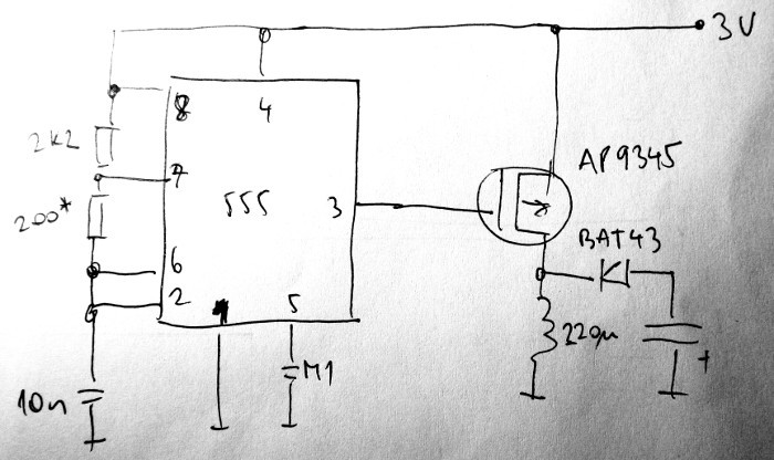
It is astable multi-vibrator with fairly high duty cycle, since gate of PMOS is active at low level relative to ground, that means low duty cycle of current flowing through inductor. The capacitor at right end of picture is the capacitor to be charged. For tests, I used 4700uF I had on hand.
With components as per schematics, 555 worked at roughly 25kHz, with approximately 35/4us duty cycle. At this duty cycle device consumed roughly 5,5mA from 3V (~1,5mA drawn by 555 itself, I have to change it to CMOS), voltage on capacitor increased. From zero to 2V in 2s, to 5V in 8,5s and to 10V in 34s. Short circuit current was 17mA. I increased the 200Ohm resistor to 290Ohm, duty cycle increased to 35/5us, short circuit to 23mA and current consumption to 7mA. Capacitor was charged to 2V in 1,6s, to 5V in 6,3s and to 10V in 23s - considerably faster, at the expense of more current drawn. Charging the 100F capacitor will take something like a half a day.
Without any kind of feedback, the converter acts roughly as power constant converter, drawing the same current regardless of output voltage. That means during phases where capacitor voltage is low, the CR2032 cell will not be overloaded, solving first problem; and buck-boost nature of the converter solves also second problem. The problem left to solve is capacitor voltage limit - this circuit has voltage ceiling a few dozens of volts and is probably able to destroy supercapacitor, if not limited.
So, problem of charging capacitor seems to be half-solved and I used NE555. Double win.
While I used back on the envelope guess-calculations in previous log, I had to take out big caliber weapon at this one
Discussions
Become a Hackaday.io Member
Create an account to leave a comment. Already have an account? Log In.
Wow, I see that great minds think alike ;) Elegant solution with 555, I however lean towards micro in my welder - for simplicity and elasticity with design.And don't mind haters, its coin cell *challenge* even when hosted on hack site.Good luck!
Are you sure? yes | no
LOL. I was planning on using a PIC in a switching converter for capacitor charging from the cell, until this morning, when I thought : maybe an LMC555 instead. Now I come home, and read you've already been there!
I like the PMOS transistor to get around the >50% duty cycle issue with the traditional 555 circuit, too.
Well done. A proper hack, indeed.
I'll stick with my PIC12LF1571 - I already chose to do the car starting example from the contest announcement - no need to steal everything :-)
The over-charge protection is interesting. In my case, where I expect the cell to be completely dead when the capacitors are finished charging, I'm going to add a TL431 shunt regulator to just clamp the capacitor voltage to some safe level and waste any excess power at the end of charging. In your case, where you might charge the cap more than once, you need a more sophisticated solution.
Are you sure? yes | no
Thanks.
I'm going to use comparator, probably some reference diode or something and a few resistors to make voltage divider and hysteresis. I need to think about how to block 555 - using pin 4 looks like logical choice, but it keeps output low, what is unwanted state here. Perhaps I just can pull/push the timing capacitor with comparator output to block the 555 from operation or block the "power" current path. I can try to shoehorn another 555 as comparator, alternatively.
Using MCU may be really simpler, after all.
Are you sure? yes | no