 jaromir.sukuba
I took an hour this afternoon and put together somehow extended version of the converter, and moved from breadboard to protoboard.
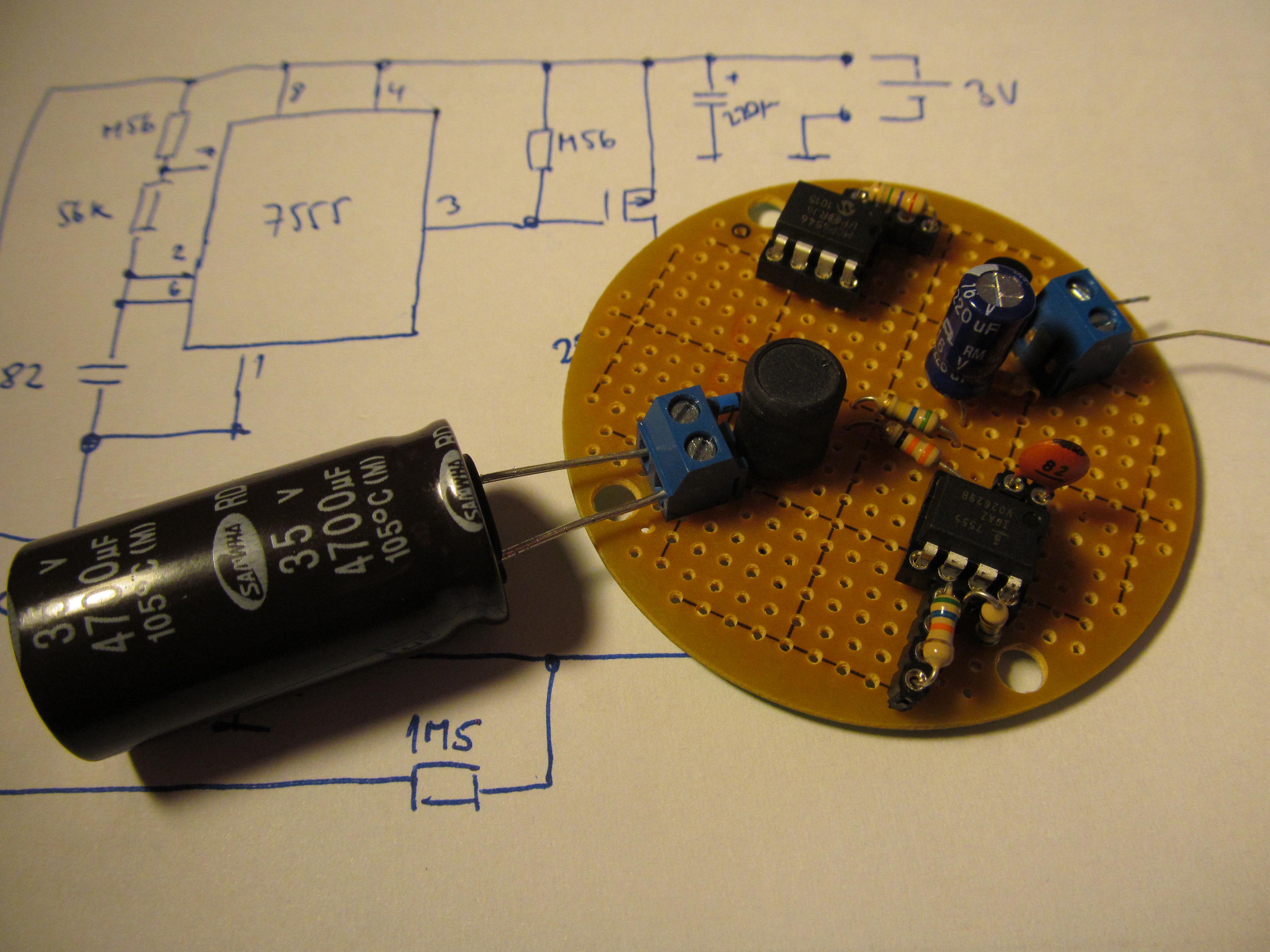
In addition to previous simple DC/DC converter, this one has five components added
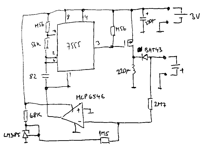
When turned on, voltage on LM385 is 1,24V, voltage on cap to be charged is zero, MCP6546 comparator "sees" more positive voltage on noninverting input, so its open-drain output is low. 7555 timer can oscillate, voltage on capacitor stars to rise; being more and more negative against circuit ground.
When voltage on LM385 versus voltage on capacitor is in ratio 1,5/2,7 - given by resistors on inverting comparator input - the voltages on both comparator inputs get equal and comparator output starts to rise up. Power supply of 7555 is cut off, transistor stay closed and circuit takes as little power as possible, mostly by current via LM385; being set to 25uA at 3V. As soon as capacitor discharges a bit, voltage on inverting comparator input rises, its output goes low, 7555 starts oscillating again and charging the capacitor again.
With components as per schematics, voltage on capacitor is stabilized at roughly 2,2V. Slightly lower than needed, but OK for experiments. Now I need to measure its efficiency and connect an actual supercap. Flux capacitor is to be added later.
Discussions
Become a Hackaday.io Member
Create an account to leave a comment. Already have an account? Log In.
I like the comparator low-side switching the 7555. When I was looking at '555 variants, I saw the LMC555 specified down to 1.5V, while most other CMOS versions are only specified to 2.0V. This might be a way to get a little more energy out of the cell, since the voltage will droop under load, especially near the end.
Are you sure? yes | no
I know the low-side switching of 7555 is somehow strange arrangement, but I tried to keep component count low. At first I tried to block oscillation at pin 2, but that drew some extra current (and CMOS 555 has still quite bit of consumption too). Turning it off solved both problems, turning it unusually from low side also gave the gate of transistor proper voltage level. It's a bit odd, but I can't find any obvious problem with it.
There is also TLC551 worth looking at, going even lower. You can feed the 551 from single silver cell.
Are you sure? yes | no