 lion mclionhead
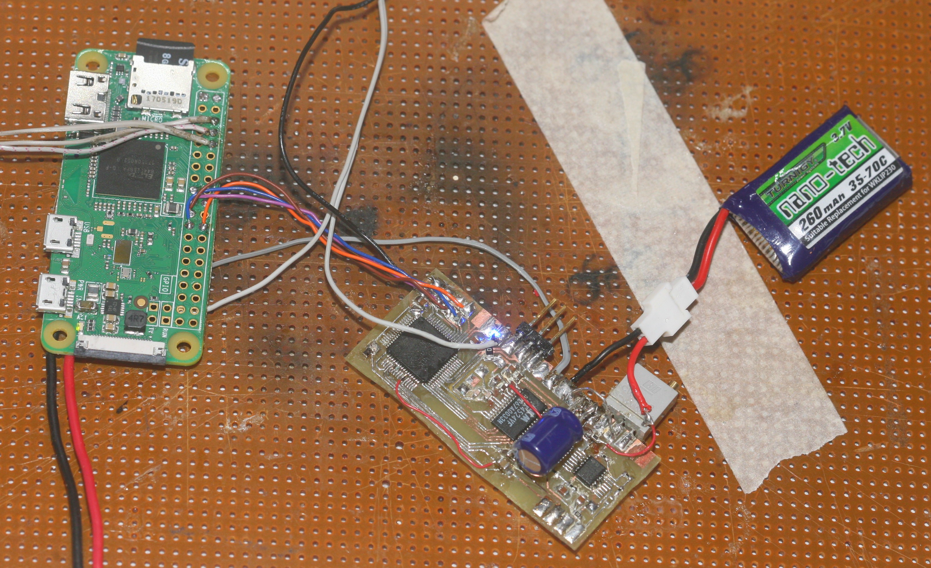
Transferring audio to the PI over SPI went relatively smoothly. 16Mhz over single ended SPI wires of 5cm worked.
On the PI, SPI only works in master mode. SPI initialization is the same as it was 5 years ago & looks like:
#define CHANNEL 0
#define SPI_BUFSIZE 2048

unsigned char buffer[SPI_BUFSIZE];

int fd = wiringPiSPISetup(CHANNEL, 16000000);
Sending a single packet on MOSI while receiving a packet on MISO:
wiringPiSPIDataRW(CHANNEL, buffer, SPI_BUFSIZE);
On the STM32F405, it starts with initializing the SPI driver for slave mode:
GPIO_InitTypeDef GPIO_InitStructure;
RCC_AHB1PeriphClockCmd(RCC_AHB1Periph_DMA1, ENABLE);
RCC_APB1PeriphClockCmd(RCC_APB1Periph_SPI3, ENABLE);
// SS
GPIO_PinAFConfig(GPIOA, GPIO_PinSource15, GPIO_AF_SPI3);
// SCK
GPIO_PinAFConfig(GPIOC, GPIO_PinSource10, GPIO_AF_SPI3);
// MISO
GPIO_PinAFConfig(GPIOC, GPIO_PinSource11, GPIO_AF_SPI3);
// MOSI
GPIO_PinAFConfig(GPIOC, GPIO_PinSource12, GPIO_AF_SPI3);

GPIO_InitStructure.GPIO_Mode = GPIO_Mode_AF;
GPIO_InitStructure.GPIO_Speed = GPIO_Speed_50MHz;
GPIO_InitStructure.GPIO_OType = GPIO_OType_PP;
GPIO_InitStructure.GPIO_PuPd  = GPIO_PuPd_DOWN;

GPIO_InitStructure.GPIO_Pin = GPIO_Pin_10 | GPIO_Pin_11 | GPIO_Pin_12;
GPIO_Init(GPIOC, &GPIO_InitStructure);

GPIO_InitStructure.GPIO_OType = GPIO_OType_OD;
GPIO_InitStructure.GPIO_PuPd  = GPIO_PuPd_UP;
GPIO_InitStructure.GPIO_Pin = GPIO_Pin_15;
GPIO_Init(GPIOA, &GPIO_InitStructure);

SPI_I2S_DeInit(SPI3);

SPI_InitTypeDef SPI_InitStructure;
SPI_InitStructure.SPI_Direction = SPI_Direction_2Lines_FullDuplex;
SPI_InitStructure.SPI_DataSize = SPI_DataSize_8b;
SPI_InitStructure.SPI_CPOL = SPI_CPOL_Low;
SPI_InitStructure.SPI_CPHA = SPI_CPHA_1Edge;
SPI_InitStructure.SPI_NSS = SPI_NSS_Hard;
SPI_InitStructure.SPI_BaudRatePrescaler = SPI_BaudRatePrescaler_16;
// SPI_InitStructure.SPI_BaudRatePrescaler = SPI_BaudRatePrescaler_32;
// SPI_InitStructure.SPI_BaudRatePrescaler = SPI_BaudRatePrescaler_256;
SPI_InitStructure.SPI_FirstBit = SPI_FirstBit_MSB;
SPI_InitStructure.SPI_CRCPolynomial = 7;

SPI_InitStructure.SPI_Mode = SPI_Mode_Slave;
SPI_InitStructure.SPI_NSS = SPI_NSS_Hard;
SPI_I2S_DeInit(SPI3);
SPI_Init(SPI3, &SPI_InitStructure);
Then, every packet needs 2 DMA transfers to be initialized for the 2 data directions:
#define DMA_RX_STREAM DMA1_Stream2
#define DMA_TX_STREAM DMA1_Stream5

#define SPI_BUFSIZE 2048
uint8_t rx_buffer[SPI_BUFSIZE];
uint8_t tx_buffer[SPI_BUFSIZE];

DMA_InitTypeDef DMA_InitStructure;
// enable receive DMA
  DMA_InitStructure.DMA_Channel = DMA_Channel_0;
  DMA_InitStructure.DMA_PeripheralBaseAddr = (uint32_t)&SPI3->DR;
DMA_InitStructure.DMA_Memory0BaseAddr = (uint32_t)rx_buffer;
DMA_InitStructure.DMA_DIR = DMA_DIR_PeripheralToMemory;
DMA_InitStructure.DMA_BufferSize = SPI_BUFSIZE;
DMA_InitStructure.DMA_PeripheralInc = DMA_PeripheralInc_Disable;
DMA_InitStructure.DMA_MemoryInc = DMA_MemoryInc_Enable;
DMA_InitStructure.DMA_PeripheralDataSize = DMA_PeripheralDataSize_Byte;
DMA_InitStructure.DMA_MemoryDataSize = DMA_MemoryDataSize_Byte;
DMA_InitStructure.DMA_Mode = DMA_Mode_Normal;
DMA_InitStructure.DMA_Priority = DMA_Priority_High;
  DMA_InitStructure.DMA_FIFOMode = DMA_FIFOMode_Enable;
  DMA_InitStructure.DMA_FIFOThreshold = DMA_FIFOThreshold_Full;
  DMA_InitStructure.DMA_MemoryBurst = DMA_MemoryBurst_Single;
  DMA_InitStructure.DMA_PeripheralBurst = DMA_PeripheralBurst_Single;

DMA_DeInit(DMA_RX_STREAM);
  DMA_Init(DMA_RX_STREAM, &DMA_InitStructure);
SPI_I2S_DMACmd(SPI3, SPI_I2S_DMAReq_Rx, ENABLE);


// enable the transmit DMA
DMA_DeInit(DMA_TX_STREAM);

DMA_InitStructure.DMA_Memory0BaseAddr = (uint32_t)tx_buffer;

DMA_InitStructure.DMA_DIR = DMA_DIR_MemoryToPeripheral;
DMA_Init(DMA_TX_STREAM, &DMA_InitStructure);
SPI_I2S_DMACmd(SPI3, SPI_I2S_DMAReq_Tx, ENABLE);

SPI_Cmd(SPI3, ENABLE);
DMA_Cmd(DMA_RX_STREAM, ENABLE);
DMA_Cmd(DMA_TX_STREAM, ENABLE);
The STM32 has to wait for DMA_RX_STREAM->NDTR to be 0 to know the packet has been transferred & it's time to reinitialize the 2 DMA transfers. It can also be done by polling (SPI3->SR & SPI_FLAG_RXNE), then reading & writing bytes to SPI3->DR. This has all probably been abstracted into Arduino for STM32.
It was finally possible to view the data in an audio editor. Amplifying it 256x revealed the lowest 16 bits & it was soul crushing noise.
Unfortunately, running SPI & writing to the SD card added a lot of noise. Disabled the preamp & just ran the ADC. It had the wifi pulses & lots of noise from SPI. It should be noted the ADC input without the preamp has to be grounded through a 10k. Leaving it open makes it an antenna & short circuiting it causes the ADC to send all 0.

What was inaudible on the phones was equivalent to an 8 bit ADC in the audio editor. Every Y pixel is equivalent to 1/65536. Going back to the dedicated 4.2V battery over a 17R & recording the ground got the noise slightly lower.
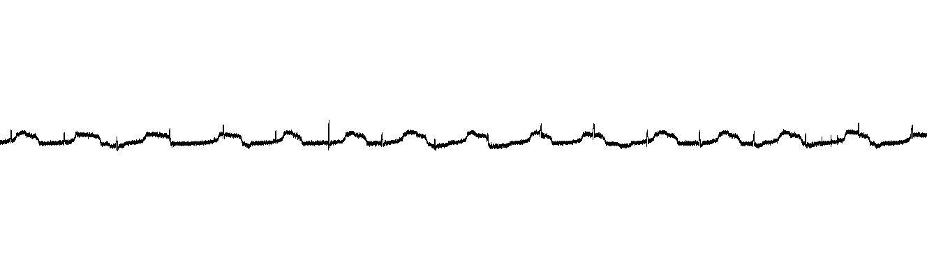
That's probably 10 bit precision. You're not going to get even 16 bit precision in this form factor, right next to the PI, with the wifi going.
Spreading it out got it up to 11 bits with no wifi pulsing.
Discussions
Become a Hackaday.io Member
Create an account to leave a comment. Already have an account? Log In.