Close
0%
0%

Self Flying Quadcopter

A fun and educational project to convert a small quadcopter to a self-flying indoor drone.

Similar projects worth following
There are lots of quadcopter hacks out there but we could not find any that convert a small, cheap quad into a self-flying drone that avoids obstacles while it explores your house all on its own. The brilliant folks over at RCgroups have figured out how to upgrade the firmware on many of them. (insert other hack-a-day project links here) we have already converted a small counterrotating heli (the Syma S107) into a self-flying heli for a class that we teach at my summer camp (www.RocksAndRobots.com) so quadcopters seemed like the obvious next step.We are using the Eachine H8 quadcopter. It already has a 6 axis IMU (inertial monitoring unit), motors and a programmable microcontroller. Distance sensors (VL53l0X) will measure the distance to objects in front, below and above the quad. An Arduino will tell the quadcopter what to do in order to avoid objects.

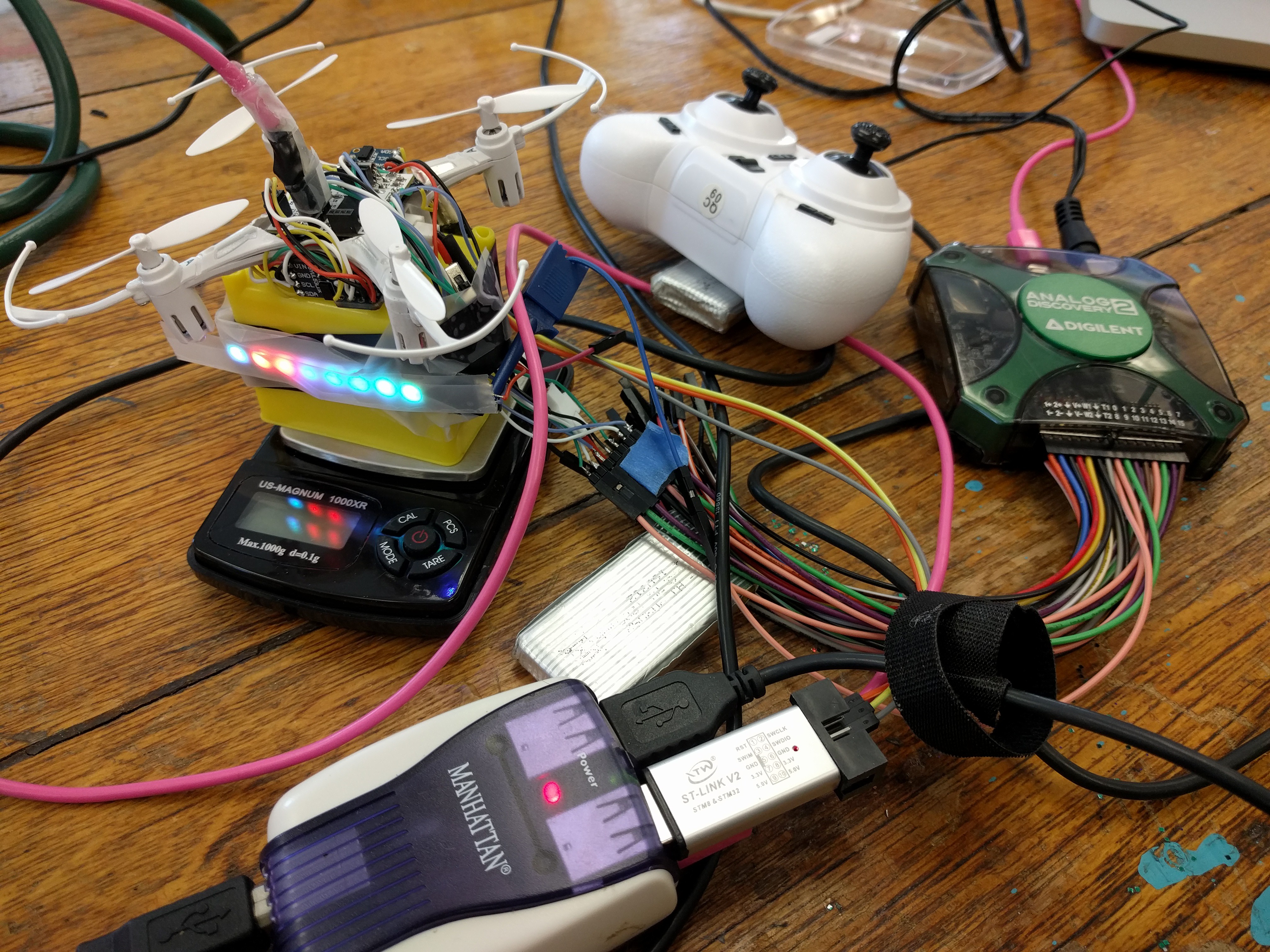
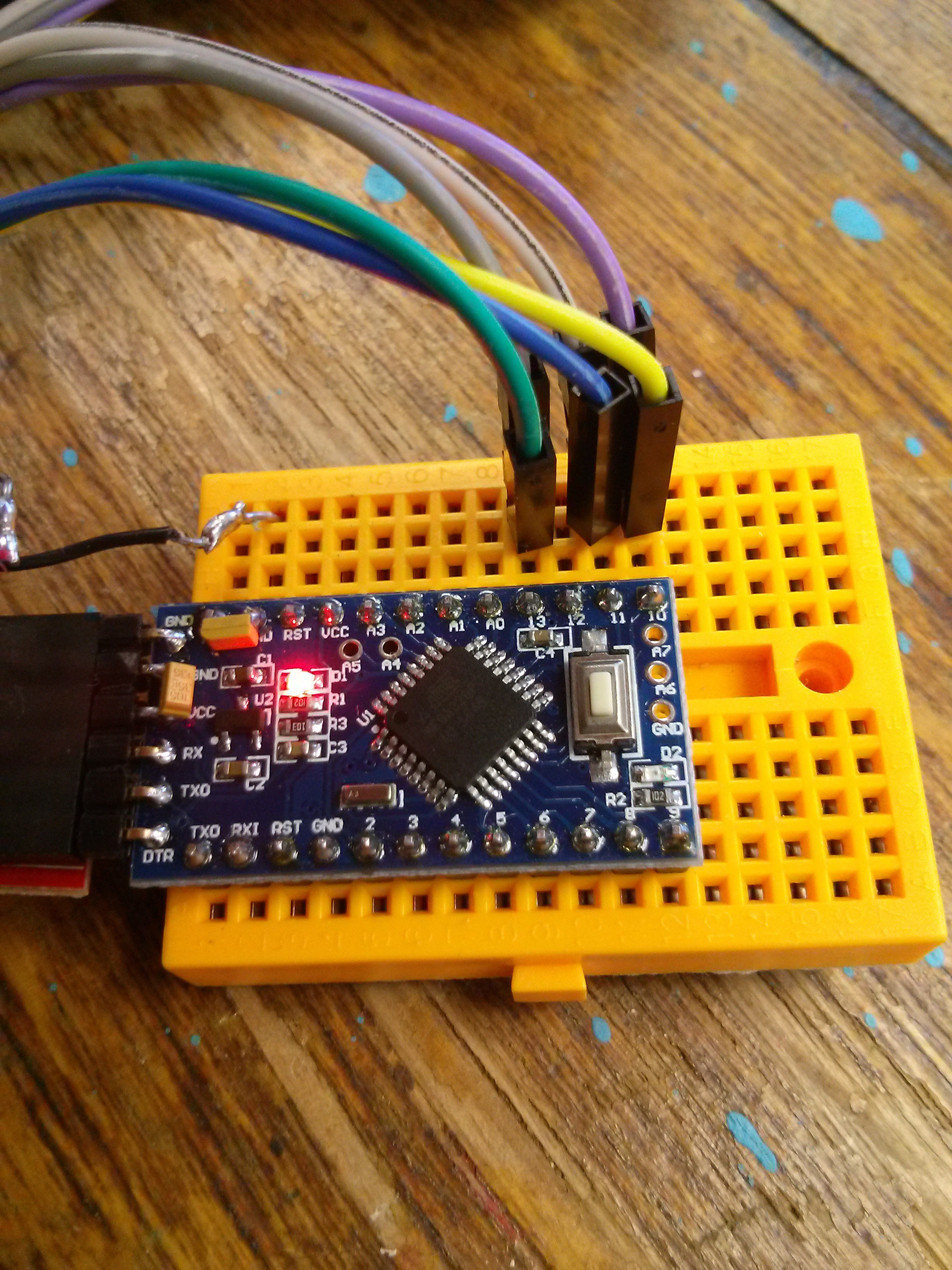
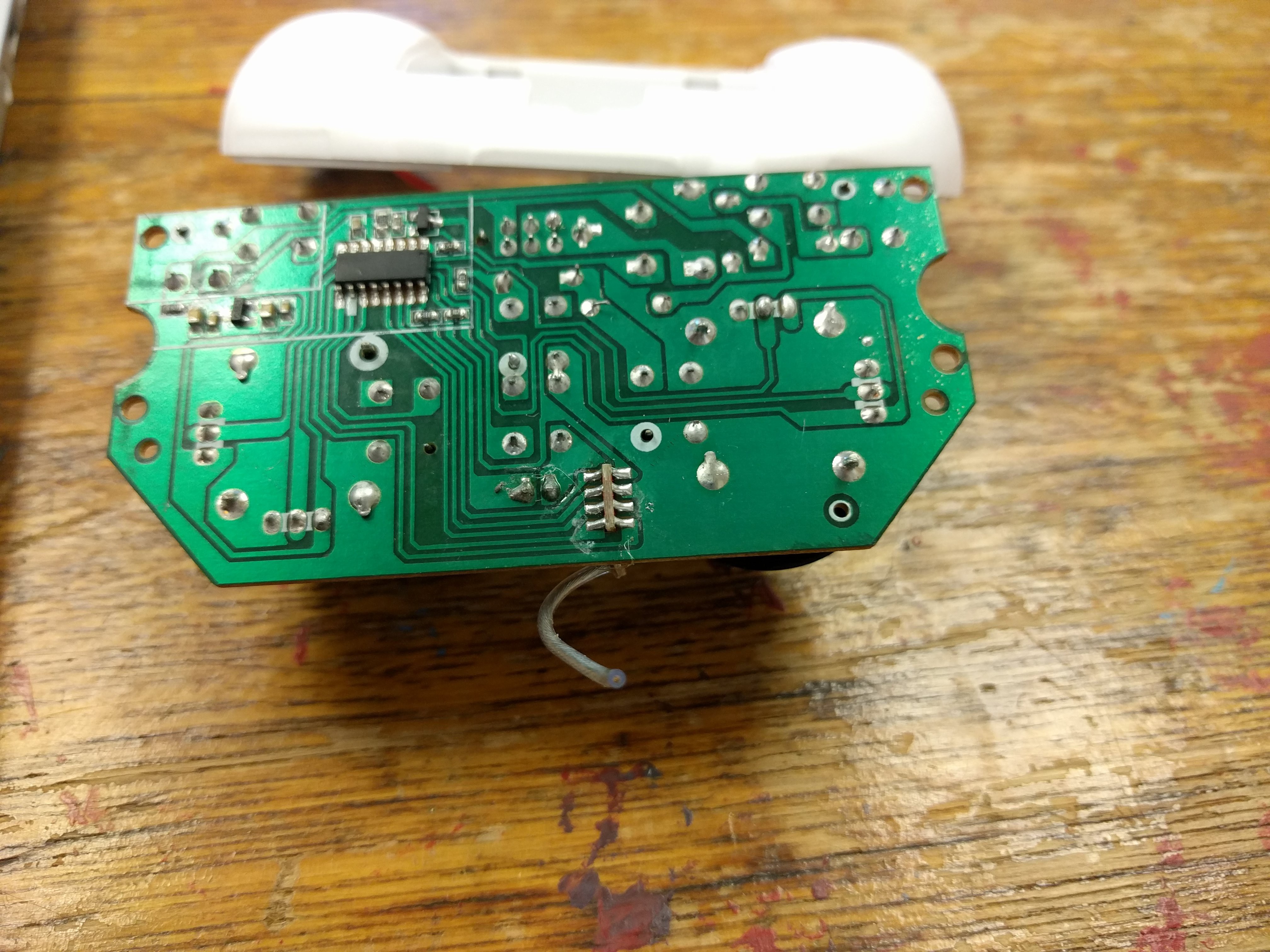
First task:  Make sure that we can communicate with the microcontroller in the  Eachine H8 Mini. See log entry Connecting with the microcontroller in the Eachine H8 mini. We will need to talk to it before we can change its mind and bend it to our will.

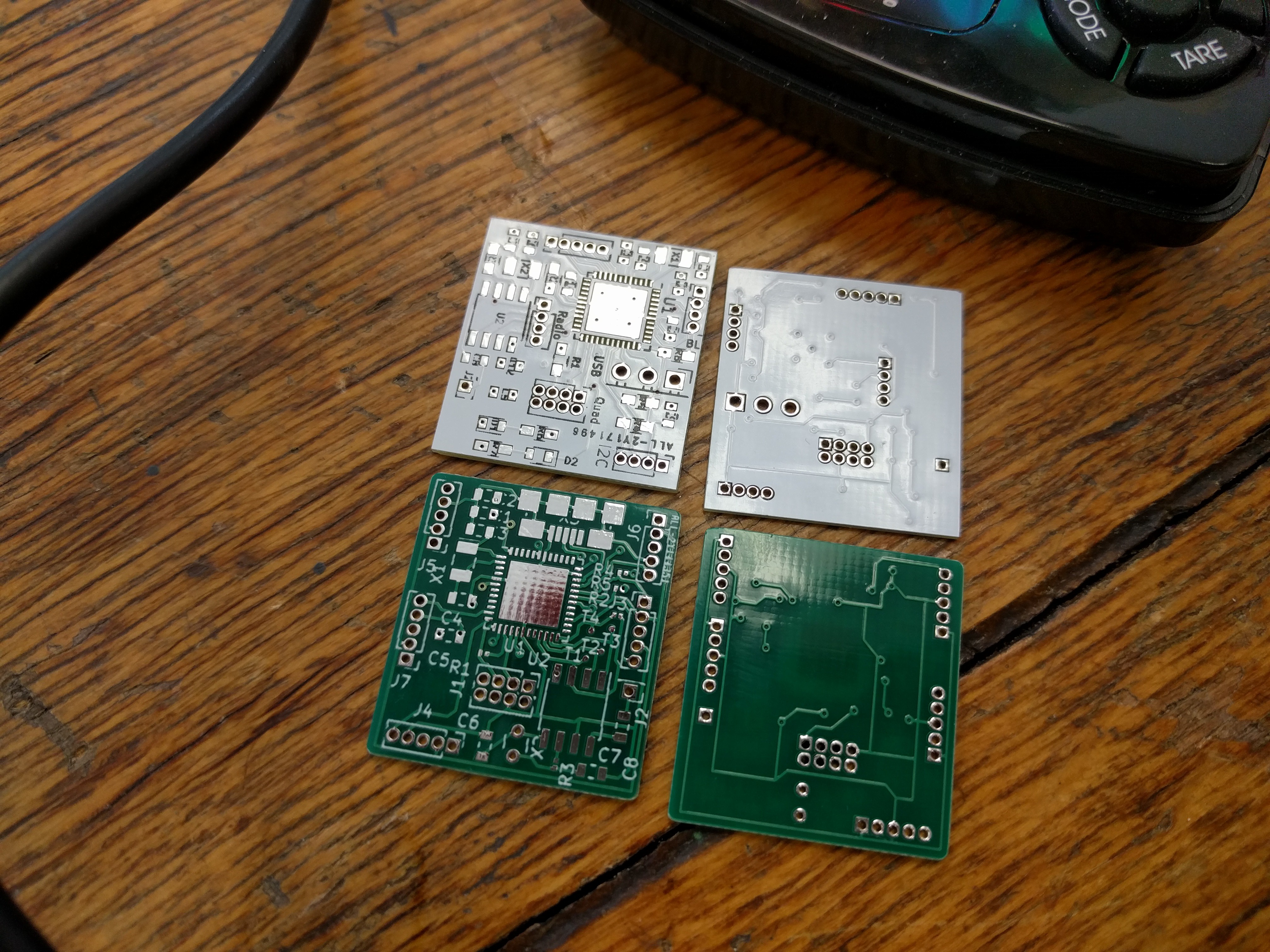
Optional step: If you are not very familiar with GitHub repositories I have added a log entry where I explain just enough to get me in trouble with any real programmers but maybe enough to help you understand which folders and files we will want to study. See Log entry Files in Github

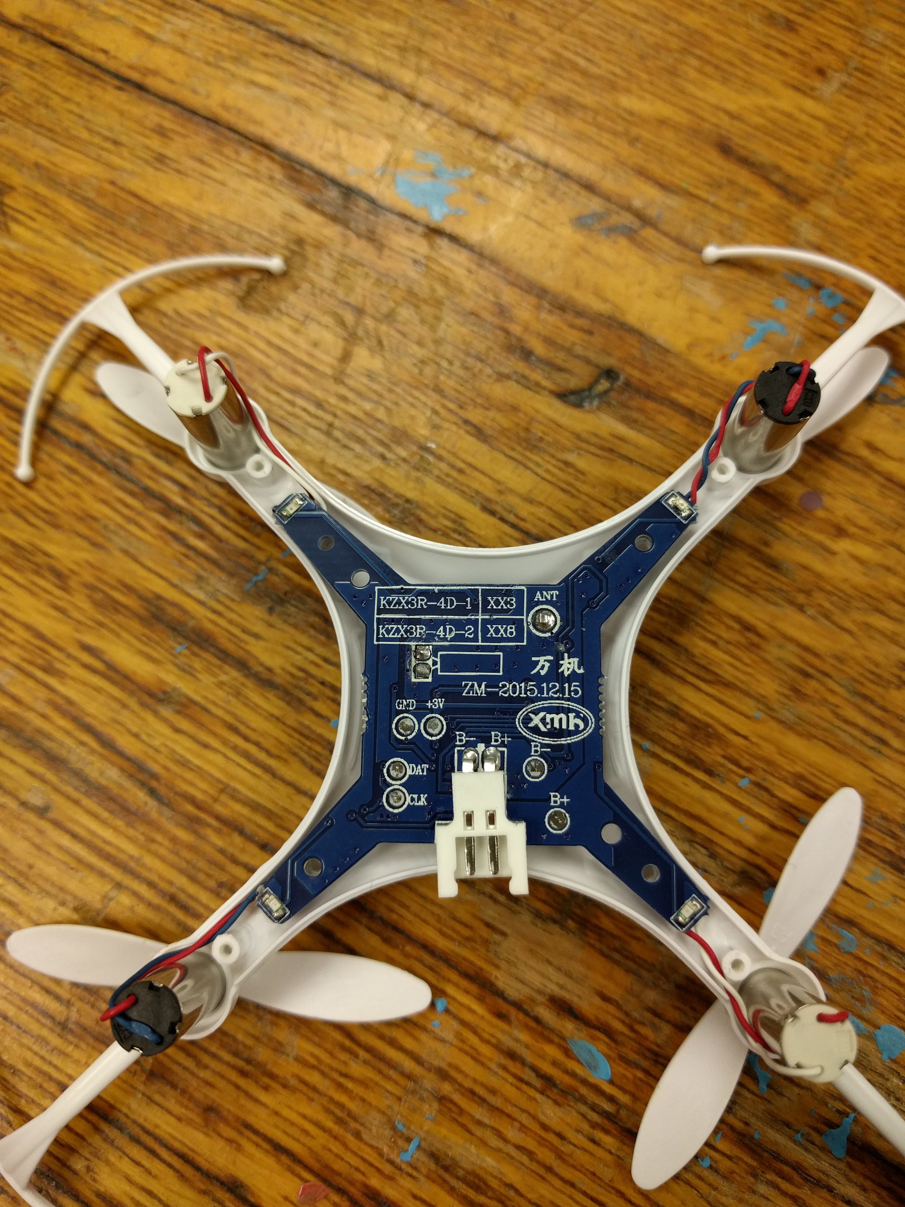
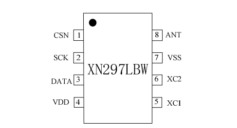
Second task: Learn about how the controller communicates with the quad. (Hint: the whole radio is in a single chip) See log entry Communication between the remote and the Quad

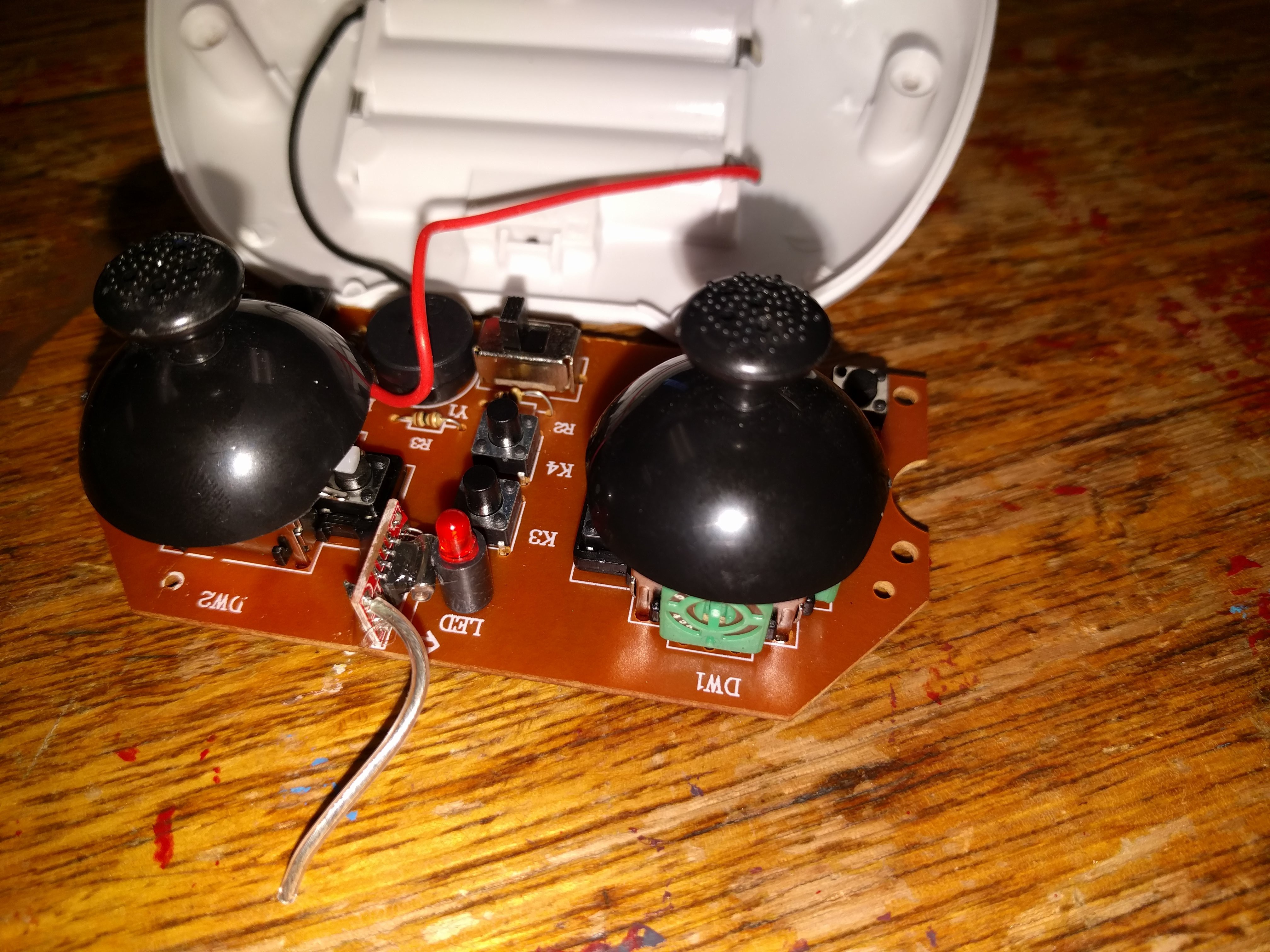
Now that we understand how the controller and the quad talk to each other we want to eavesdrop on their conversation. See log entry Snooping on SPI

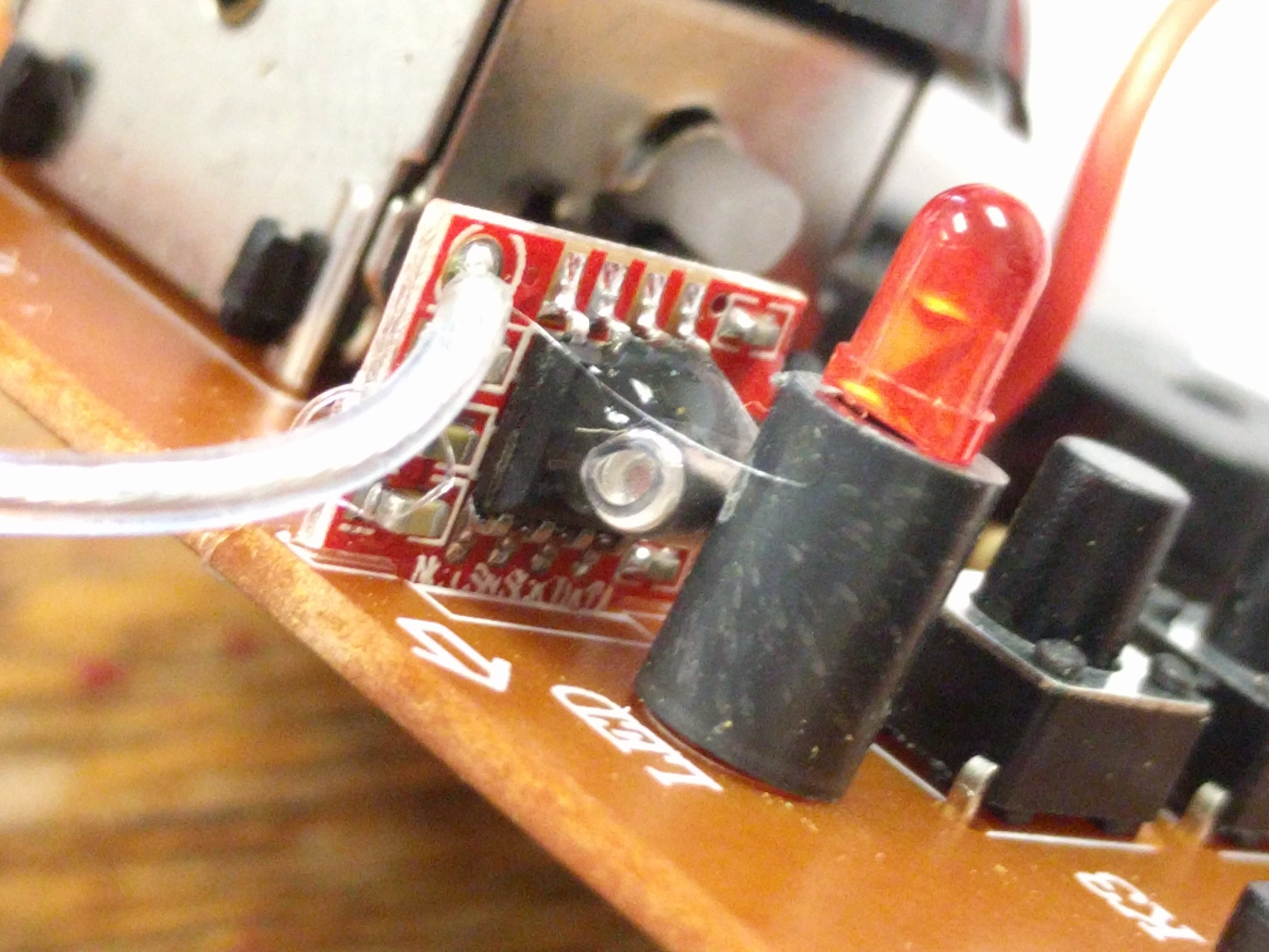
Paul is digging deep into the code that Silverxxx provided to see if we can inject our own data into the stream. 

  • New quadcopter prototype hardware for June

    Paul Haas06/11/2018 at 16:29 0 comments

    We are on our second version of the PCB.

    Modified Eachine H8 Mini "blueboard" quadcopter with an Arduino M0 clone grafted on top. The Arduino acts as the Cortex doing higher level control such as path planning, and collision avoidance, while reading from the laser range finders that act as primitive eyes. The original STM32F0x is  running a modified version of Silverware acting as the brainstem to handle basic functions like balance. With the debugging connections this prototype weighs to much to actually fly, so it is on a test stand which includes a scale, so we can measure lift. Once we measure the maximum lift, we will know if this prototype can be made to fly, or if we need to wait for the next version.

    The USB hub is connected to a Chromebook running Gallium (a derivative of Ubuntu). The ST-Link V2 programmer allows us to reboot or reprogram the STM32F0x brain stem. The pink USB cable coming out the 3 pin mail header on top is used to reboot or reprogram the Arduino M0 Cortex. There are five VL53L0X laser range finders connected to the cortex over an I2C bus. They point up, down, left, right, and forward. The colored lights on the test stand are a row of 8 Adafruit NeoPixels. The next version will use smaller pixels that are actually mounted on the quad copter, and thus will be available for use during flight.

    The Digilent Analog Discovery 2 is configured as a protocol analyzer monitoring the SPI buses between cortex and the brain stem, and between the cortex and the XN297L radio receiver for the remote control seen in the background.

    The Arduino acts as a man in the middle between the XN297L radio and the brain stem. With the standard Arduino IDE, it will be possible to program the quadcopter for anything from  autonomous tasks, such as being a hovering work light, to being fully remote controlled, with many levels of assistive flight in between. For example, the quadcopter could take off and land by itself, but otherwise fly under remote control at a fixed height, and avoid running into walls.  

    The blurry tape over the NeoPixels is acting as an optical diffuser.  Without the diffuser, the point source LEDs produce annoying afterimages that persist after I switch from looking at the LEDs to looking at the computer.

    Examples of the older green board and newer white board PCB prototypes for the self flying quad copter. They are based on the Adafruit Feather M0 design and can be programmed with the Arduino IDE configured for an Adafruit Feather M0. 

    To make documentation easier, the white board does not use any GPIO pins that aren't easily accessible on the Adafruit Feather M0.  In the prototype, there is a battery extension cable with built in test points and a power switch.

  • 3-Wire SPI - A deep dive

    George Albercook12/27/2017 at 04:14 0 comments

    The XN297L radio chip uses an uncommon implementation of SPI.  SPI typically uses four wires to achieve synchronize communication they are Clock, MOSI and MISO and ground.  Sparkfun has a great tutorial on serial communication.

    When two devices communicate with a synchronized protocol one has to control the clock. That one is called the master.  Now the master can either send or receive data so that leaves several possibilities. Typically, in SPI one pin will act as the master (control the clock) when it is sending data, but when it is receiving data it will be the slave. This are denoted Master Out Slave In (MOSI). A second pin is called MISO (Master In Slave Out) meaning that pin controls the clock when data is coming in but is the slave when data is going out. One benefit of this configuration is that Data can be going both ways at the same time.

    In order to do this four wires are required. MOSI, MISO, Clock and Ground but the XN297L does not use all four. It runs in a much less common configuration that only allows data to go in one direction at a time. This is called 3-wire SPI.  The XN297L will always act as the slave so its' communication pin is called SOSI (Slave out, Slave In).  This pin connects to a pin on the master which is called MOMI (Master Out, Master In). 

    In order to get our microcontroller to us this configuration we will have to tell it which of its' SPI pins will become MOMI and to ignore the other pin. The easy way to do this is to cheat and copy some example code that does it. Unfortunately, we could not find such an example so we put on our miner hardhats (the ones with lamps on them) kissed our wives and descended into the depths of the microcontroller data sheets.

  • Our first attempts to take control

    George Albercook12/12/2017 at 23:13 0 comments

    We want to start small with our transformation of an Eachine H8 mini into a zombie drone.  The idea is to add a distance sensor to the bottom of the quad and use the distance values to control the altitude.  Paul's first goal was to find the place in the code that waits for the throttle to increase the first time after the quad and controller have paired. He them inserted a call to the failloop() function when the throttle is increased. 

    Within Silverware>scr there are several files that provide communication for different quads. There was one called drv_xn297_3wire.c within it Paul found a function xn_readpayload. Payload refers to the contents of the communication packet.  

    He then searched within scr for all examples of xn_readpayload. He found that when the file rx_bayang_protocol_telemetry.c called xn_readpayload it communicated with our Eachine H8 mini. (Cleverly he did it by breaking them one at a time until he found the correct one).

    Next he added the failloop to make it stop as soon as the throttle was increased.

    The relevant part of the packet starts after 165

         if (rxdata[0] == 165)
                     rx[3] =
                         ((rxdata[8] & 0x0003) * 256 +
                          rxdata[9]) * 0.000976562f;
    +     if (((rxdata[8] & 0x0003) * 256 + rxdata[9]) > 50 ) {
    +     failloop(5);
    + }
     

    He added the three lines starting with "+"

  • Snooping on SPI

    George Albercook12/12/2017 at 20:24 0 comments

    We had some Arduino Mini Pros around from another project. The seem perfect for listening in on the data that is being sent between the controller and the Quad. Here is the pinout of the Arduino Mini Pro and the way that we wired one of them into the SPI communication bus in the remote control.

    (Ignore the red lines)
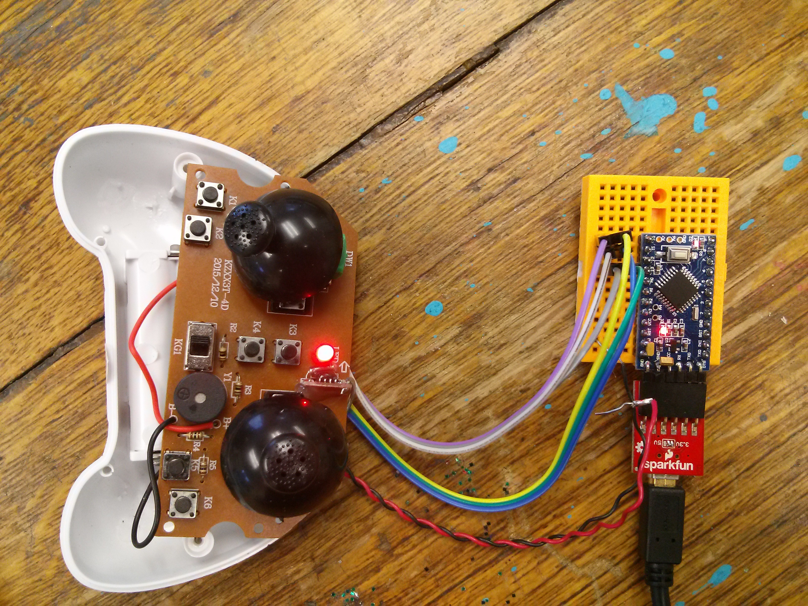
    Notice on Pins 10,11,12 and 13 SS, MOSI, MISO and clock. Since we are using the three-wire configuration we don't need MISO on pin 12.

    It turns out that their are several flavors of the SPI bus. The XN297L uses a half-duplex version and only need three wires. 

    The wires that we brought out from the remote control PCB are as follows

    Purple and yellow is Chip Select

    Blue and White(with black strip) is MOSI

    Green and Gray are Clock

    Here is how we set it up to snoop.

    Here is another view for those following along with the home game.

    We checked and the Eachine will still pair with the remote and fly.

  • Connecting with the microcontroller in the Eachine H8 mini

    George Albercook12/11/2017 at 18:56 0 comments

    The good folks over at RCGroups.com have already reverse engineered the firmware for the Eachine H8 mini (and many other quads as well). We followed these step-by-step instructions.

    The kind manufacturers have even labeled the pads that we need to solder our programmer to. 

    Unfortunately the labels are wrong. DAT and CLK are switched. This is all documented at the above link. After a bit of downloading, installing and reading parts of the files in the GitHub repository we were able to connect and reprogram the Eachine H8 mini.

    This we did in only a few hours. Don't be discouraged if this sort of thing takes you more time, more tries and results in bonking your head against the table. We have all done that. The reason that this was so quick was of all the hard work of silver13 and many others over at RCGroups.com.

    To convince ourselves that we had reprogrammed the Eachine we inserted a command called failloop() at the beginning of the firmware. failloop() is an infinite loop that does nothing but blink the LEDs.

  • Files in Git Hub

    George Albercook12/08/2017 at 21:14 0 comments

    I find that Git Hub repositories can be very confusing. Silverxxx from RCGroups created a repositoryfor all of the files needed to upgrade the firmware on the Eachine H8 mini.

    I wanted to go over how I became familiar with the folders and want they mean. 

    Librariesrelease2 years ago
    Silverwarebuzzer works in fail condition now3 months ago
    Utilitiesrelease2 years ago
    binupdated binaries6 months ago
    gccfix gcc "soft lpf filters"a year ago
    .gitattributescause c and h files to be detected as text files7 months ago
    .gitignorerelease2 years ago
    .travis.ymltravisa year ago
    INSTALL.mdUpdate INSTALL.md4 months ago
    README.mdUpdate README.md8 months ago

    Starting at the top the In this case the Libraries are files that tell the system about the specific microcontroller that is used on the Eachine H8 mini.

    Silverware>>scr here is the good stuff. The source code. You probably don't need to look into this if all you wanted to do was reflash the firmware the quadcopter you probably don't need to look into the guts here but we will probably need to study them inorder to make the kinds of modifications that we want to.

    Utilities seem to have to do with the drivers for the programming dongle.

    bin contains the hex files that can be directly flashed to the Eachine.

    gcc contains information for the gcc compiler like the makefile so that it knows how to make hex files that the microcontroller will understand. 

    All of the files that start with a "." are what GitHub uses to maintain the repository.

    INSTALL.md and README.md are text files with human readable instructions. Read them   

  • Communication between the remote and the Quad.

    George Albercook12/08/2017 at 21:12 1 comment

    Talking to the chip that does the communication between the remote control and the quad:

    RF communication is done with the XN297L 2.4GH transceiver chip. We want to insert ourselves between the controls on the remote and the XN297L chip also on the remote.

    Here is the controller opened up.

    That little daughter board standing on edge has is the XN297L on it. 

    Here is a closeup.

    From the pinout we can tell which pins we want to intercept.

    We will cut in on the back side of the board

    If you follow the traces from the Blue, Green and Yellow wires you can see that the traces on the PCB are cut. The other ends of the traces go to the chip. 

    Purple and yellow is Chip Select

    Blue and White(with black strip) is MOSI

    Green and Gray are Clock

    Now we need to be able to read write signals to our wires. The protocol used is called SPI. The flavor that we are using is three wire SPI. So now we will set up an Arduino to speak SPI.

View all 7 project logs

Enjoy this project?

Share

Discussions

Similar Projects

Does this project spark your interest?

Become a member to follow this project and never miss any updates