The MCU has lots of ports:
- Unknown barrel jack, "Aux Temp"
- RJ11, 6-Position 4-Conductor (6P4C), "Display"
- PS/2, "Sensor Net"
- DB9, "Modem"
- DB9, "Computer"
- Barrel jack, "Power"
The display board just has a matching RJ11 port, but with only the outer two wires connected - "6P2C". The center two are unconnected, but can be connected through a varistor to ground with a jumper. Maybe an upgraded version of this board speaks RS-232 over these wires? I don't claim to know.
Behind each RJ11 port is a pair of ferrite beads...
Side note. I learned that a ferrite bead, like a grounded capacitor, filters out high-frequency noise from a circuit. But it does so by, essentially, acting like an antenna. It increases inductance, and thereby impedance. A capacitor, on the other hand, will lower the impedance, so isn't as good for communication lines.
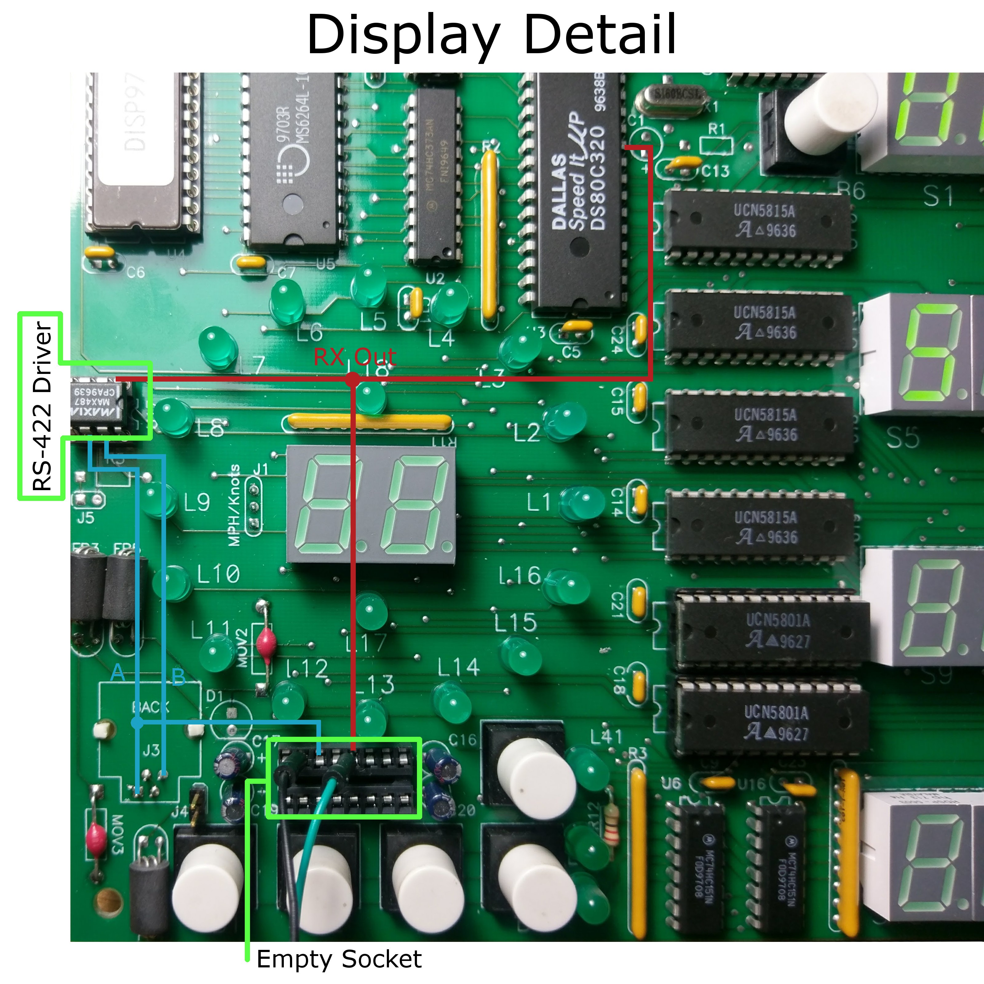
... And behind the ferrite beads, a MAX487 chip. The MAX487 has something to teach me about serial communication. PC Serial, known as RS-232, is referenced to ground. But RS-422 and RS-485 (an old Macintosh standard) use differential voltage. You've got an "A" and a "B" output, and if A>B by 200mV, it's a "1". If A<B by 200mV, it's a "0". So it's also got some built-in hysteresis. Sounds pretty great to me! Unfortunately, a bit of a pain.
Poking around with the multimeter some more, I find that all the important pins except "B" on the Display board's serial driver are connected to an unpopulated chip socket! Perhaps the hypothetical "upgrade" board spoke RS-232 instead, allowing the chips to be swapped. I put a probe on the "Receiver Output" (RO), which should nicely decode the RS-422 signal for me.
Later, it may be trivially easy to remove the MAX487 entirely, and spoof the RO line with the ESP8266.
Discussions
Become a Hackaday.io Member
Create an account to leave a comment. Already have an account? Log In.