 Christoph Tack
DTMF will be generated using Direct Digital Synthesis (DDS)
The first implementation will be done with Adafruit ProTrinket 3V, which runs at 12MHz. The final implementation will use some ATTiny at 8MHz.
where
- fo = output frequency
- M = phase accumulator
- fc = clock frequency
- n = bitwidth of phase accumulator
Frequency resolution
So the frequency resolution is :
The allowable frequency tolerance for the DTMF frequencies is ±1,5 %. This is maximum 10.4Hz for 697Hz, which is the lowest DTMF tone.
For 12MHz, fast PWM, the interrupt frequency is 47KHz, phase accumulator is 16-bit. The frequency resolution is (12MHz / 256) / 65536 = 0.7Hz. This is more than enough. Also for 8MHz system, the frequency resolution of the DDS is sufficient for this application.
Minimum clock frequency
There is also an upper limit to the frequency that can be generated. Practically:
For DTMF, the maximum frequency is 1633Hz, so fc, which is the frequency of the timer interrupt, should be at least 4.9KHz.
Comparison of PWM-modes for generating DDS
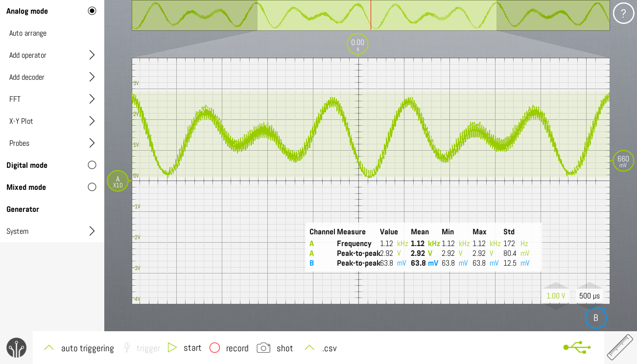
Below you can find two screenshots that show the difference between fast-PWM and phase-correct-PWM on the Adafruit ProTrinket 3V. Clearly, the phase correct PWM will need much more filtering to get a clean output signal. That's because the interrupt frequency in fast-PWM-mode is twice the interrupt frequency of the phase-correct-PWM mode.
The low pass filter used in all the screenshots is just a simple first order RC-filter: 330ohm with 100nF. These were just some parts lying around on my desk. The cutoff frequency is 4.8KHz.


Sine table
To avoid the time consuming operation of calculating a sine wave in real time, the values are precalculated and stored in flash.
The original implementation of which you can see screenshots above had a sine table with 256 values. To save space in flash, this has been reduced to 128 values. There's no noticeable difference in the output.
The pwm resolution of timer2 in the AVRMEGA is 8bit. The original sine table was normalized to 8bit, i.e. the sine values were in the range [0..255]. For application in DTMF, two sine waves must be added. The 8bit sine wave values will overflow. To prevent this, the sine table has been normalized to 7bit, i.e. [0..127].
Final output
Discussions
Become a Hackaday.io Member
Create an account to leave a comment. Already have an account? Log In.