Close
0%
0%

desperate firefly

Silicon Laboratories inc. sell MCU named Busy Bee, I decided to give it a try by transforming one in desperate firefly.

Similar projects worth following
I knew Silicon Labs for their RF products but until recently I ignored their MCU existence. The fact is they sell 8 bits MCU. The EFM8BB10F8G-SOIC16 as for less than 1$ more peripherals than Microchip ones for the same price and run faster. The 'BB' in part number stand for Busy Bee. They also use brand names likes Sleepy Bee, Laser Bee and Universal Bee. Someone in their marketing team likes bees. I decided to give it a try and as first project I obviously chose the inevitable blinky. But a blinky with a twist. This one blink SOS morse code, hence its name. I designed it to run as long as possible on a single CR2032 button cell. At this time it is blinking for 13 days and I expect it to blink at least 20 days. Here I present the details of the project.

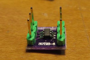
The hardware is only 5 components including cell and its holder.

1 1K smd resistor

1  small red led

1  EFM8BB10F8G-SOIC16  MCU

1 CR2032 battery holder

1 CR2032 button cell

The MCU is glued on the back of cell holder using hot glue.  Resistor and  LED are glued on back of MCU using cyanate glue. See picture in images galery.

  • death of firefly

    Jacques12/17/2017 at 14:24 0 comments

    Firefly died last night without getting any answer to its desperate calls. It lastest less than 16 days. 4 days less than expected. Maybe the 240mah capacity was over evaluated. It was a no brand cell from China without specifications. The 240mah was taken from a known brand.

    signing off.

  • PIC10F200 version

    Jacques12/17/2017 at 00:32 0 comments

    I was not done yet. I decided to create  a PIC10F200 version of desperate firefly.

    The PIC10F200 is the simplest MCU available.  As for peripherals it only have an 8 bits timer and a watchdog timer. 256x12bits words  of flash memory and 16 bytes of RAM. It run on an 4Mhz internal oscillator. PIC execute instructions in 4 clocks cycles, this means 1 million instructions par second at most because branch and call needs 8 clocks cycles. Although the Fsys frequency can't be reduce to save power, the MCU can be placed in a low power mode using <i>sleep</i> machine code instruction.  When in sleep mode the MCU can be reset by the watchdog timer overrun. So in this version the strategy was to put the MCU in sleep mode and use the watchdog timer to reset it at regular interval, set the new status of the LED according to message bitstream stored in flash memory and then put the MCU back in sleep.

    The MPLABX project is included in PIC10F200_version on the github repository

    I prefer to code these little MCU in assembler.

       include "P10F200.INC"
        
        
        ; LED connected on GP2
        constant LED=(1<<GP2)  
        ; sos message bit counter
        constant count=16 ; this is a variable at address 16.
        
        code 
        org 0
    ; hardware init
        movlw (1<<NOT_GPWU)|(1<<PSA)|4
        OPTION
        movlw ~LED
        TRIS  GPIO
        btfss STATUS,NOT_TO ; if a power reset clear count
        goto next_bit
        clrf count
        
    next_bit:
        movfw count
        call sos
        xorlw 0
        skpz 
        bcf GPIO,GP2
        skpnz
        bsf GPIO,GP2
        incf count
        movlw .28
        xorwf count,W
        skpnz
        clrf count
        sleep
    
    sos: ; data  message 0=LEDoff, 1=LEDon
        addwf PCL,F
        dt 1,0,1,0,1,0,1,1,1,0,1,1,1,0,1,1,1,0,1,0,1,0,1,0,0,0,0,0
        
        end
        

    The measured current drain is very similar to the EFM8BB10F8G version.

  • EFM8 family

    Jacques12/15/2017 at 22:46 0 comments

    The EFM8 MCU family is based on CIP-51 core which is a modernized version of Intel MCS-51, the core of 8051 MCU. CIP-51 core run faster . Here a document comparing CIP-51 performance with MCS-51 . It accept an external clock up to 25Mhz and have an internal oscillator running at 24.5 Mhz and a low frequency one at 80Khz. The core can be run from the HFO or LFO and there is frequency divisor at the output of the LFO as well as one for system clock, such at the CPU can be run at a very low frequency.  The instruction set is 100% compatible with 8051.  The MCU used in this project have 8KB flash and 512 bytes RAM. This RAM is splitted in 2 parts as 256 bytes regular RAM and 256 bytes XRAM.

    The peripherals set as nothing to surprise one used to work with MCU. It include ADC, UART, TIMERS, analog comparators and 1 PCA (Programmable Counter Array) . The PCA is used for signal capture,PWM and frequency generation. It is equiped with a 16 bit counter and 3 comparator channels.

    Configurator

    The configurator is a visual tool to setup peripherals configuration and pinout assigment through the crossbar. The crossbar take in charge the connections betwen peripherals and MCU I/O pins. This visual tool save on hand written code. When the tool is closed the configurator generate a set of files containing code for the basic MCU configuration.

    I concluded the first log on an image of configurator perspective.  Now we will use this tool for configuration of  this project.

    1. Selecting the clock source to Low Frequency Oscillator divided by 32.
    2. Next we must enable the LFO and we divide its frequency by 8. Hence the system clock will be at 80Khz/8/32=312.5Hertz. That is fast enough for this application and it grealty reduce current drain.
    3. Now we will disable the Watchdog Timer.
    4. The LED is connected on pin 8 alias P1.3 We will configure it as Open drain output and skip the crossbar assignment. Skipped means that the crossbar won't assign any peripheral to this pin so it can be controlled by software.
    5. We are done but before closing the configurator, we check Problems tab. there is a warning.  The message crossbar not enabled tell us there is a problem with this config. The crossbar must be enabled even though there is no peripheral connected to any pin. But there is a bug in the configurator in Outline window when selecting CROSSBAR or any of its register, the   Properties window stay blank.
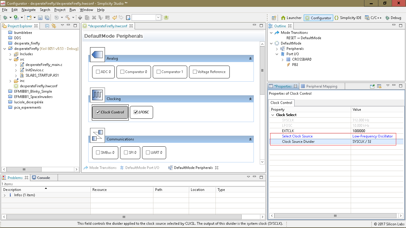
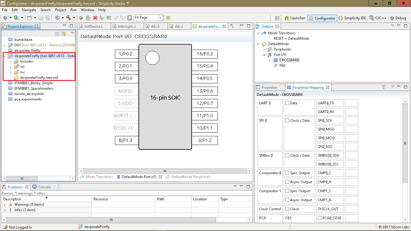
      I found a way around this bug. By double-clicking the warning message the Properties window display correctly.
    6. To terminate a configuration we close the despearteFirefly.hwconf file. It take a few seconds for the configurator to generate the files.  Two C files desparateFirefly_main.c and InitDevice.c and one assembly file SILABS_STARTUP.A51.  The file desperateFirefly.hwconf is the configurator database. Double-clicking this file reopen the Configurator.
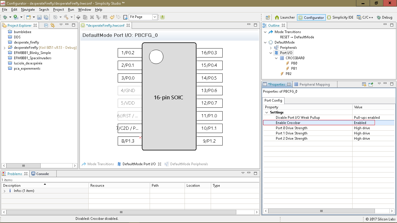
      It is instructive to look at the 3 source code files. For this simple project there not much in it nevertheless we have saved a lot of reference manual reading. Now only thing left to do is add our code in the file desperateFirefly_main.c
      // bit pattern to generate SOS morse code: dit,dit,dit,dah,dah,dah,dit,dit,dit
      code char sos[4]={0xab,0xbb,0xaa,0};
      
      //-----------------------------------------------------------------------------
      // main() Routine
      // ----------------------------------------------------------------------------
      int main (void)
      {
          unsigned char b,c;
      
      // Call hardware initialization routine
        enter_DefaultMode_from_RESET();
         b=0;
        while (1) 
        {
          c=sos[b/8]&(1<<(7-b%8));
          b++;
          if (b==28) b=0;
          if (c)
              P1&=~(1<<3); // port 1 pin 3 latch low LED ON
          else
              P1|=(1<<3); // port 1 pin 3 latch high  LED OFF
        }
      
      }
      

     about the code

    The SOS message is stored in

    code char sos[4]={0xab,0xbb,0xaa,0};

    note de compiler directive code  , At first I had used const instead expecting that the compiler would...

    Read more »

  • Project creation in Simplicity Studio

    Jacques12/15/2017 at 02:25 0 comments

    First step was to download and install Simplicity Studio.  It is a free download requiring only an account registration. It is based on Eclipse IDE and provide Keil C51 compiler also free.

    In spite of its name it is not simple as Arduino IDE. It is a full features professionnal tool. At first launch a guided tour is offered.

    project creation

    Right of tool bar there is a serie of icons. These are perspective selector icon. To create a project:

    1. Click on launcher icon
    2. From launcher perspective click new solution button.
    3. Custom solution is already selected. click ok
    4. Back to new solution perspective enter CPU name and rename custom solution to desperate firefly.

      now click New Project .  Click next on the first 2 dialogs.

      On the next dialog enter the project name (space not allowed) and click next again.

      Now click finish in the last dialog.

    After a few seconds the IDE fall in configurator perspective. It will be the subject of next log of this project.

View all 4 project logs

Enjoy this project?

Share

Discussions

Mike Szczys wrote 12/15/2017 at 22:15 point

Nice work, don't forget to submit it to the Coin Cell Challenge!

  Are you sure? yes | no

Similar Projects

Does this project spark your interest?

Become a member to follow this project and never miss any updates