 Jacques
The EFM8 MCU family is based on CIP-51 core which is a modernized version of Intel MCS-51, the core of 8051 MCU. CIP-51 core run faster . Here a document comparing CIP-51 performance with MCS-51 . It accept an external clock up to 25Mhz and have an internal oscillator running at 24.5 Mhz and a low frequency one at 80Khz. The core can be run from the HFO or LFO and there is frequency divisor at the output of the LFO as well as one for system clock, such at the CPU can be run at a very low frequency. The instruction set is 100% compatible with 8051. The MCU used in this project have 8KB flash and 512 bytes RAM. This RAM is splitted in 2 parts as 256 bytes regular RAM and 256 bytes XRAM.
The peripherals set as nothing to surprise one used to work with MCU. It include ADC, UART, TIMERS, analog comparators and 1 PCA (Programmable Counter Array) . The PCA is used for signal capture,PWM and frequency generation. It is equiped with a 16 bit counter and 3 comparator channels.
Configurator
The configurator is a visual tool to setup peripherals configuration and pinout assigment through the crossbar. The crossbar take in charge the connections betwen peripherals and MCU I/O pins. This visual tool save on hand written code. When the tool is closed the configurator generate a set of files containing code for the basic MCU configuration.
I concluded the first log on an image of configurator perspective. Now we will use this tool for configuration of this project.
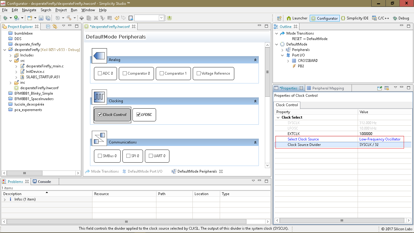
- Selecting the clock source to Low Frequency Oscillator divided by 32.
![]()
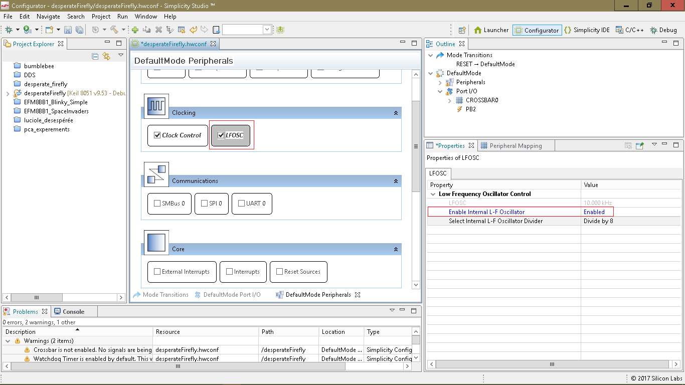
- Next we must enable the LFO and we divide its frequency by 8. Hence the system clock will be at 80Khz/8/32=312.5Hertz. That is fast enough for this application and it grealty reduce current drain.
![]()
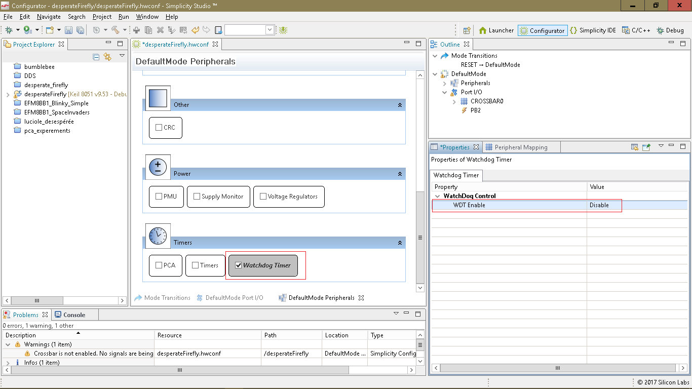
- Now we will disable the Watchdog Timer.
![]()
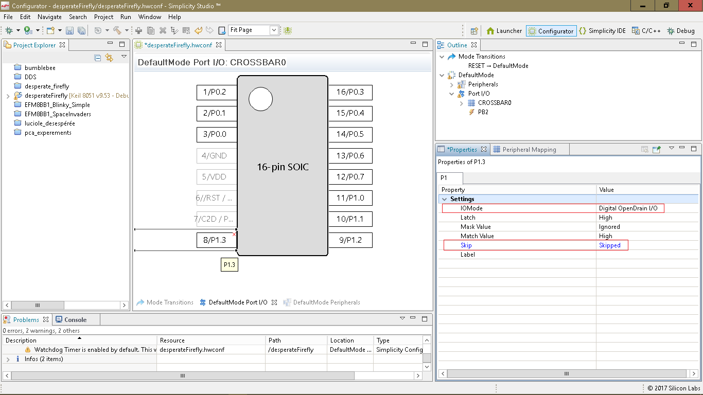
- The LED is connected on pin 8 alias P1.3 We will configure it as Open drain output and skip the crossbar assignment. Skipped means that the crossbar won't assign any peripheral to this pin so it can be controlled by software.
![]()
- We are done but before closing the configurator, we check Problems tab. there is a warning. The message crossbar not enabled tell us there is a problem with this config. The crossbar must be enabled even though there is no peripheral connected to any pin. But there is a bug in the configurator in Outline window when selecting CROSSBAR or any of its register, the Properties window stay blank.
![]() I found a way around this bug. By double-clicking the warning message the Properties window display correctly.
I found a way around this bug. By double-clicking the warning message the Properties window display correctly.![]()
- To terminate a configuration we close the despearteFirefly.hwconf file. It take a few seconds for the configurator to generate the files. Two C files desparateFirefly_main.c and InitDevice.c and one assembly file SILABS_STARTUP.A51. The file desperateFirefly.hwconf is the configurator database. Double-clicking this file reopen the Configurator.
![]() It is instructive to look at the 3 source code files. For this simple project there not much in it nevertheless we have saved a lot of reference manual reading. Now only thing left to do is add our code in the file desperateFirefly_main.c
It is instructive to look at the 3 source code files. For this simple project there not much in it nevertheless we have saved a lot of reference manual reading. Now only thing left to do is add our code in the file desperateFirefly_main.c// bit pattern to generate SOS morse code: dit,dit,dit,dah,dah,dah,dit,dit,dit code char sos[4]={0xab,0xbb,0xaa,0}; //----------------------------------------------------------------------------- // main() Routine // ---------------------------------------------------------------------------- int main (void) { unsigned char b,c; // Call hardware initialization routine enter_DefaultMode_from_RESET(); b=0; while (1) { c=sos[b/8]&(1<<(7-b%8)); b++; if (b==28) b=0; if (c) P1&=~(1<<3); // port 1 pin 3 latch low LED ON else P1|=(1<<3); // port 1 pin 3 latch high LED OFF } }
 I found a way around this bug. By double-clicking the warning message the Properties window display correctly.
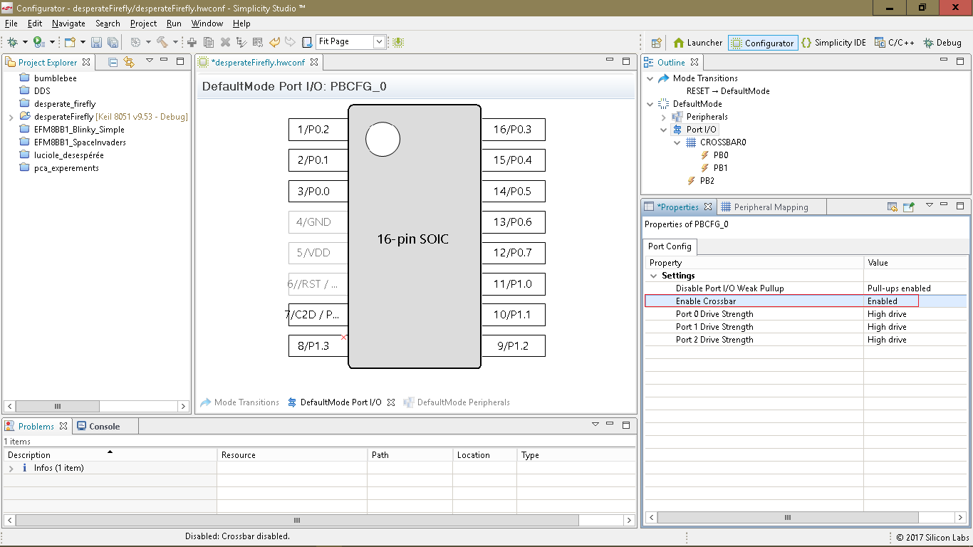
 It is instructive to look at the 3 source code files. For this simple project there not much in it nevertheless we have saved a lot of reference manual reading. Now only thing left to do is add our code in the file desperateFirefly_main.c
 about the code
The SOS message is stored in
code char sos[4]={0xab,0xbb,0xaa,0};
note de compiler directive code , At first I had used const instead expecting that the compiler would keep the array in flash memory. But it didn't, the array was copied from flash to RAM at startup. To avoid this code must be used instead of const. There is others directives to inform the compiler in which memory region to place the data. One should not expect to find information about the compiler in the IDE help. One should go to Keil website for that.
Keil Cx51 compiler user's guide
The char array is in fact dealed with as a bit array. Each bit is a unit of time. 0 means LED off and 1 for LED on.
The bit is the time unit. Each symbols are seperate by 1 bit LED off. A dit is 1 bit LED on. A dah is 3 bits LED on and there is 5 bits LED off at the end of SOS call before loop back. Notice that there is no delay loop. With a Fsys =312.5hertz, extracting the next bit from the array take enough time for a bit duration of about 0.2 second. As the message length is 28 bits including pause the SOS is repeated at about every 6 seconds.
I measured a current drain at about 120µA with LED off and 1.1ma with LED on. On 28 bits, 15 are LED on and 13 are LED off. (120µA*13+1100µA*15)/28= 566µA mean current drain. For a cell capacity of 240maH it should take about 423 Hours to drain the cell, or 18 days. But as the cell voltage drop, the LED current drop too. I expect the cell to last more than 18 days.
A this moment desperate firefly has been calling SOS for 14 days. I will add a log to this project when it will stop blinking.
Conclusion
Consedering feature/price and speed, these MCU are a good deal compared to PIC 8 bitters. The problem is the lack documentation. Silicon Laboratories is a small player in the market of MCU and one should not expect the same community support as for others MCU like the ones from Microchip/Atmel.
There is a few bug in the configurator. Another problem is with the programmer called US Debug Adapter by Silicon Labs. But I couldn't use the debug feature the connection failed each time I tried.
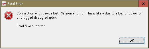 I didn't search the solution to this problem yet.
Hoping this short introduction to simplicity studio and EFM8 MCU will be of any use to someone,
Regards,
Jacques
Discussions
Become a Hackaday.io Member
Create an account to leave a comment. Already have an account? Log In.