 Ben
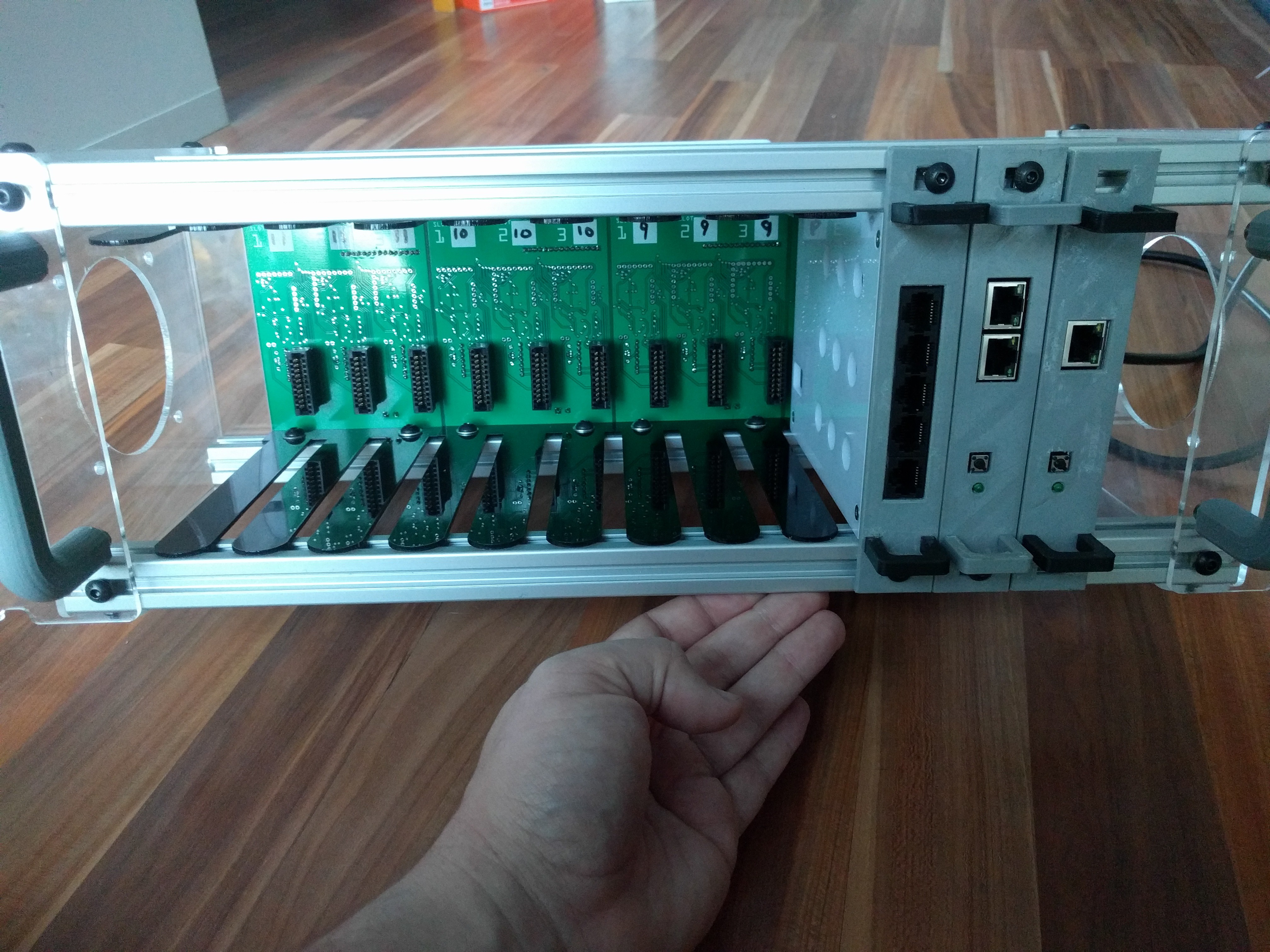
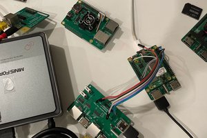
BenThe idea behind Caddyshack is to have a rackmountable (or free standing) chassis to put Raspberry Pis or other SBCs into one location.
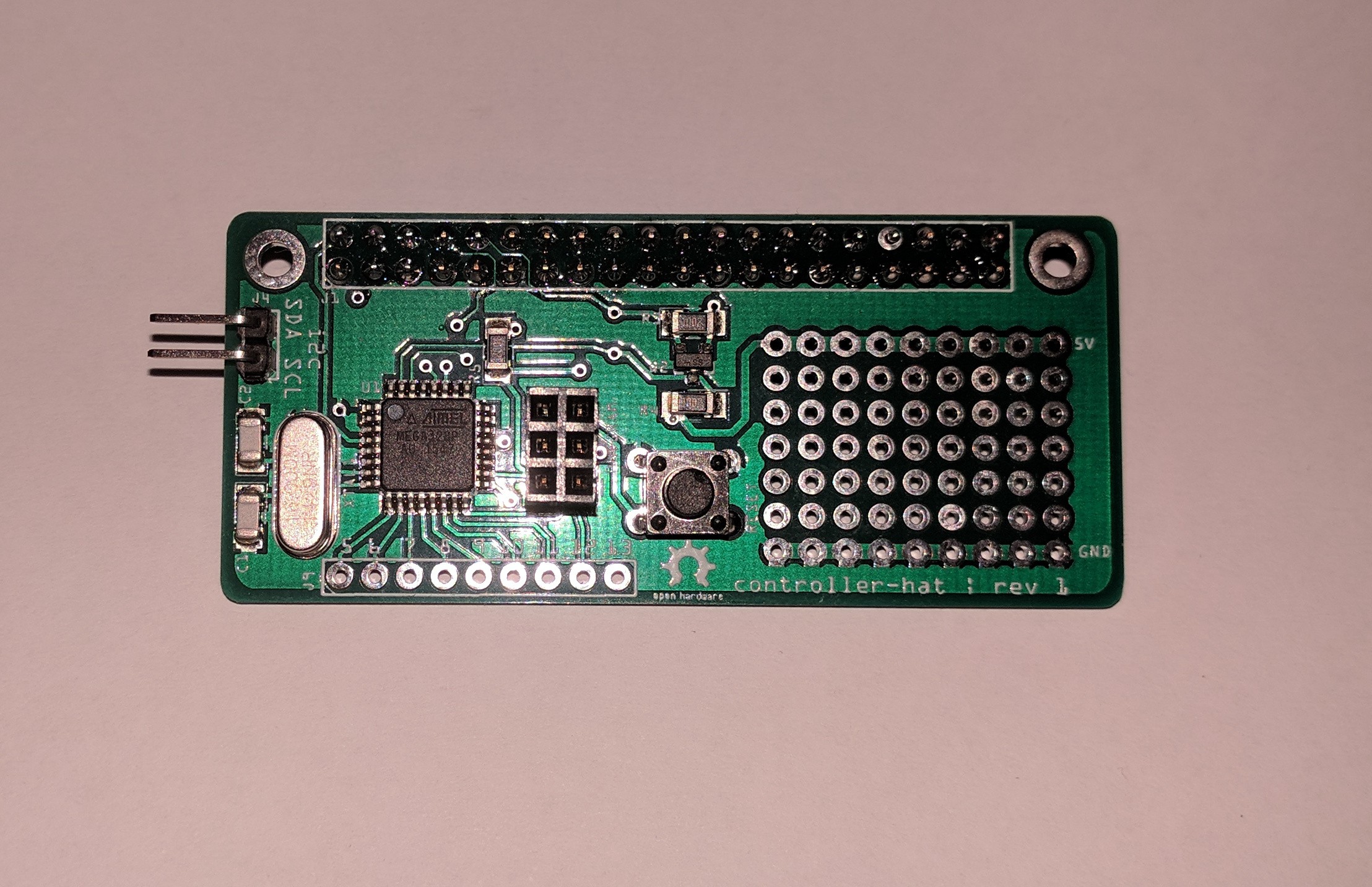
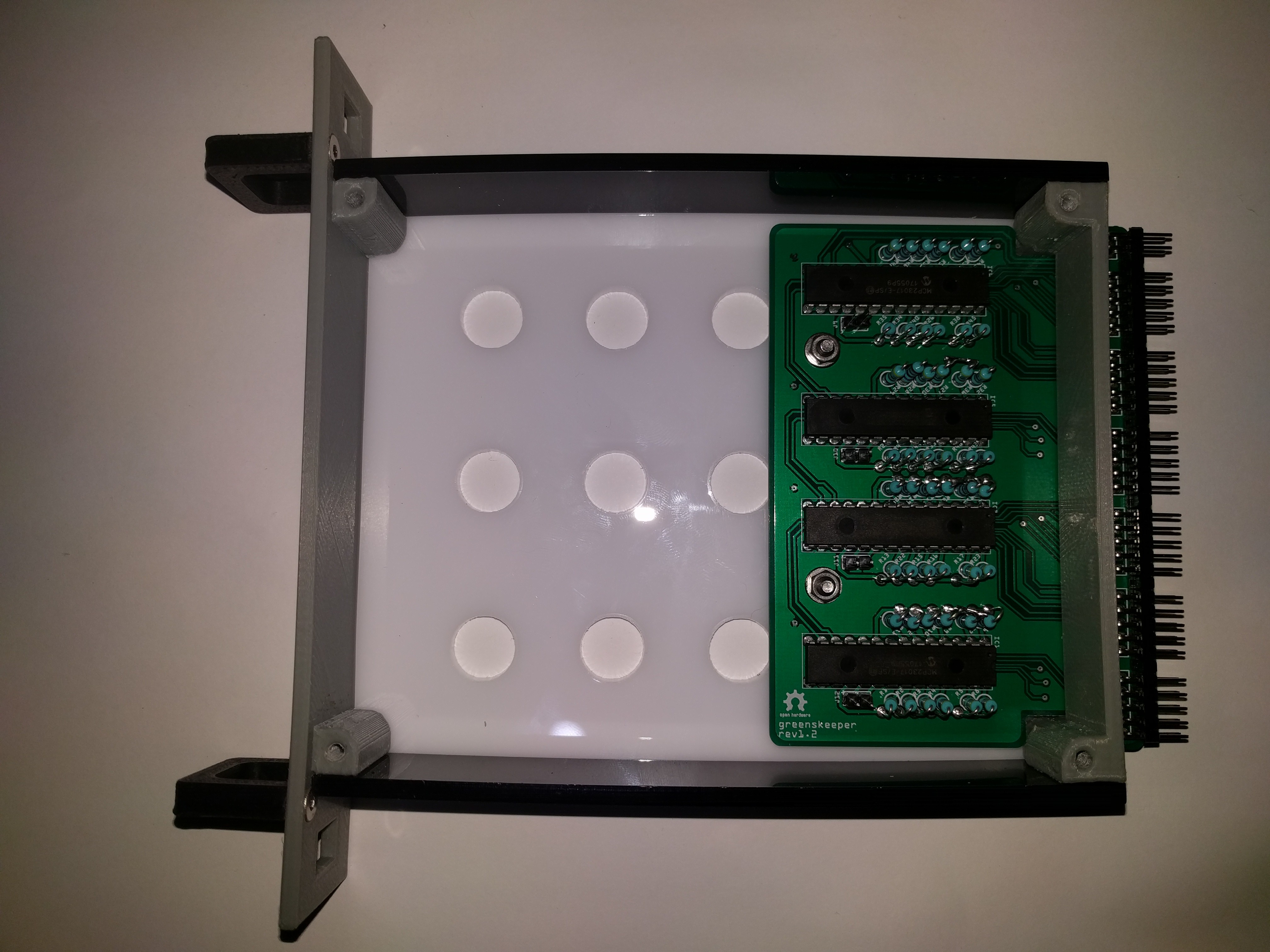
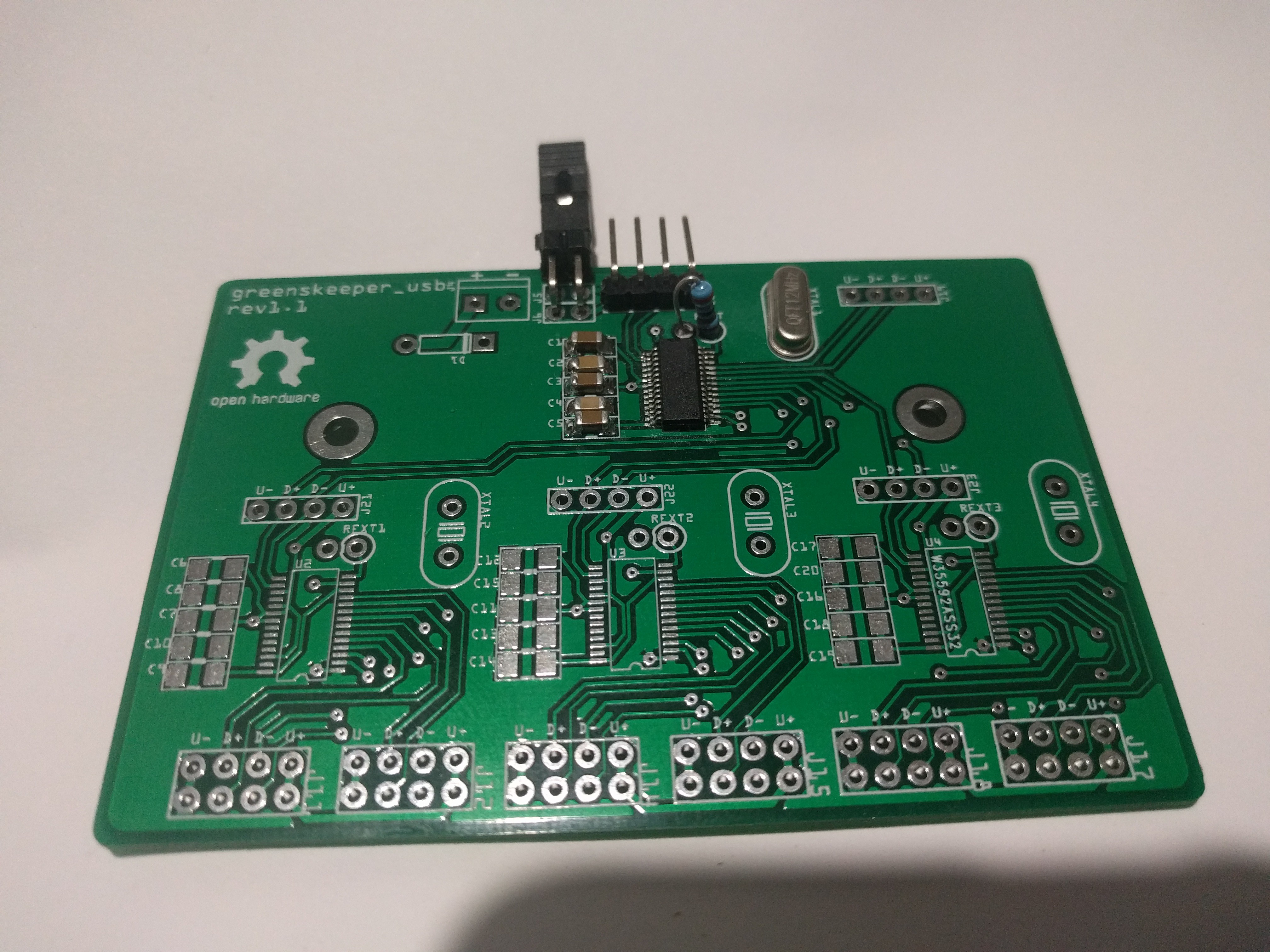
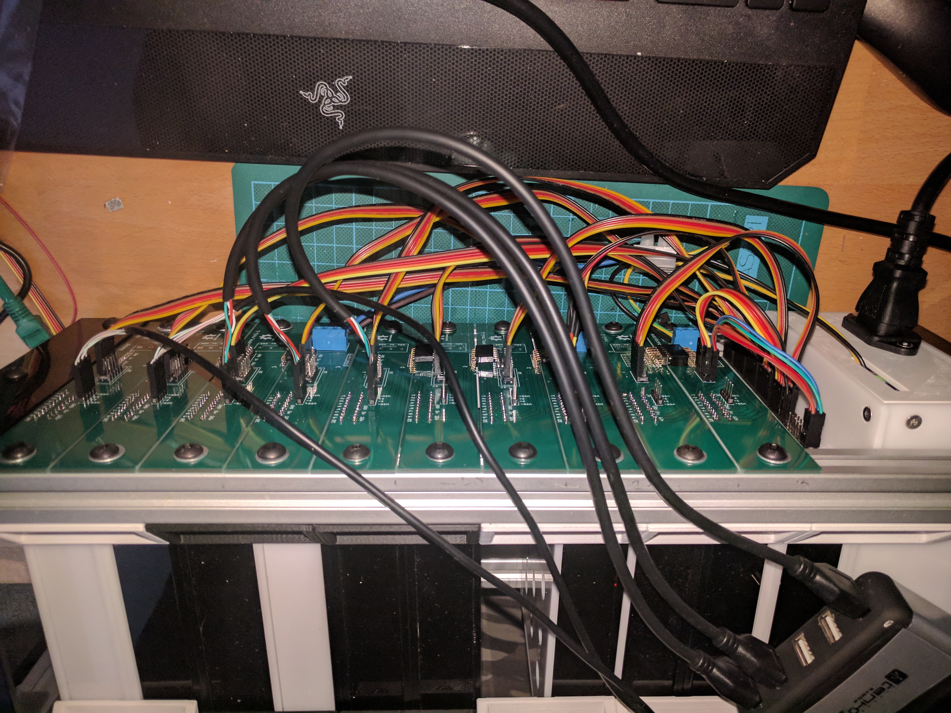
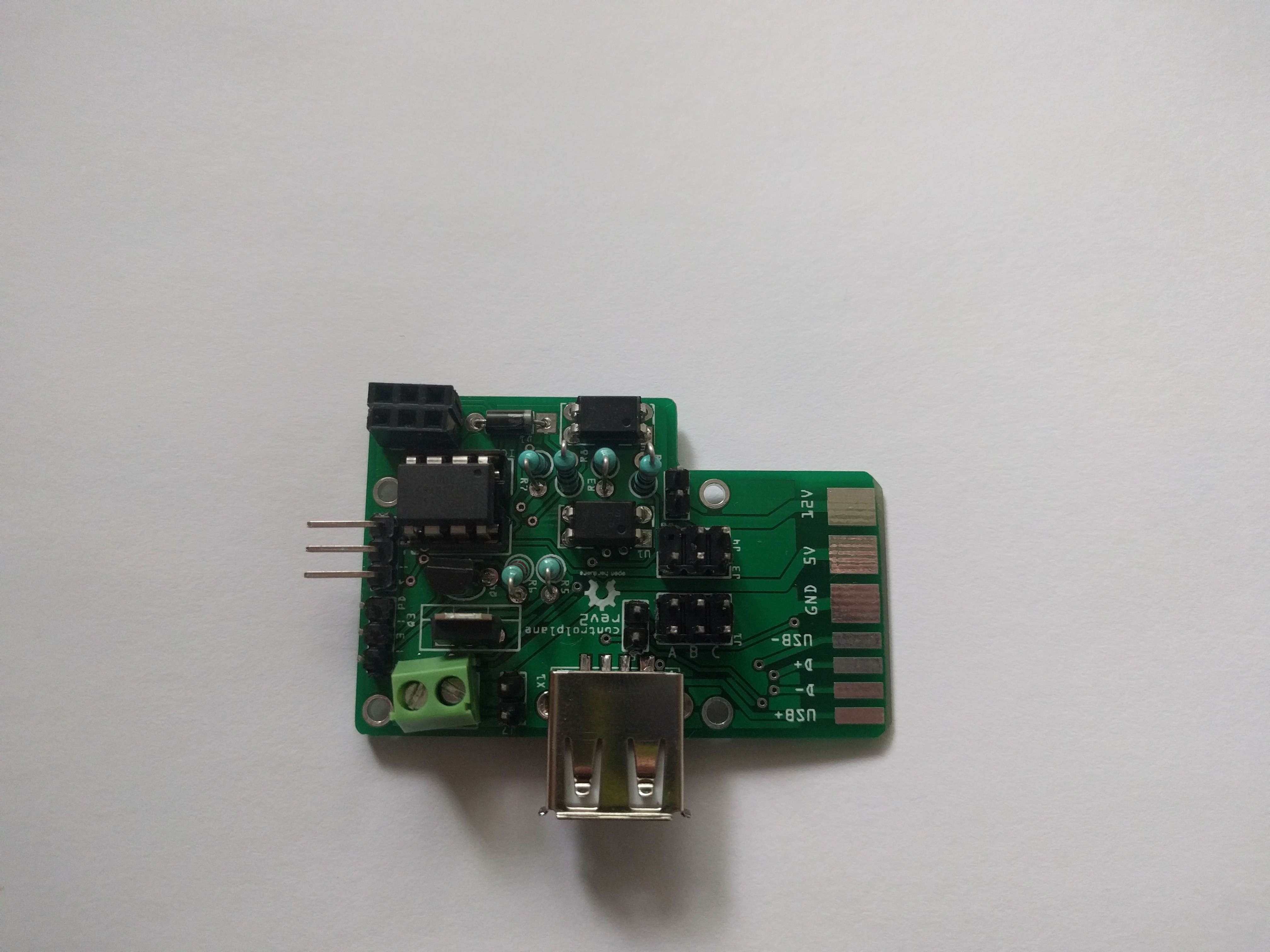
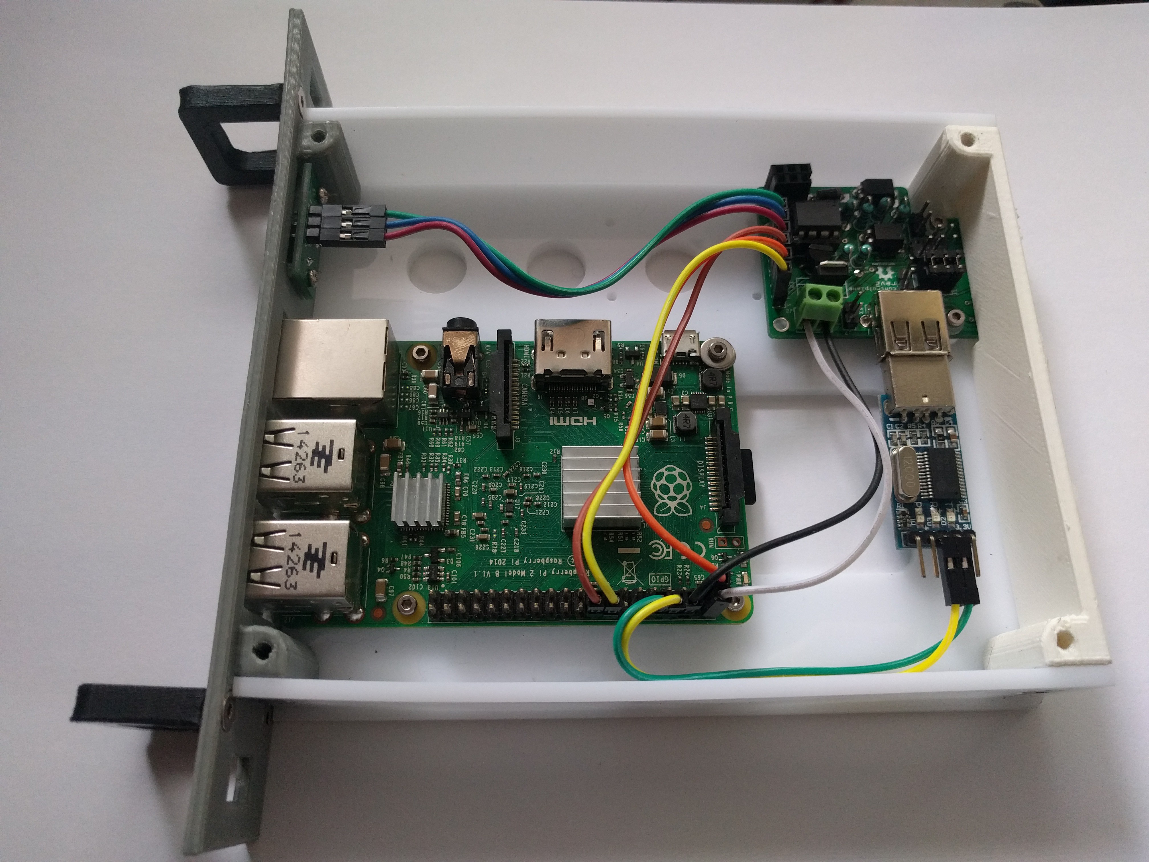
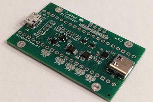
Caddyshack has control software called Greenskeeper, which runs on a dedicated Raspberry Pi, with a module that runs off the side called Greenskeeper which is 4 i2c port expanders, and a 12 port USB hub.
The port expanders are used to determine the power state of each Caddy, turn on/off the Caddy, or determine the type of Caddy that is in a particular slot. The Greenskeeper software can read and control each caddy, and determine if the caddy has a USB->SER adapter installed and will load up shellinabox sessions for those that do have one.
This is Caddyshack
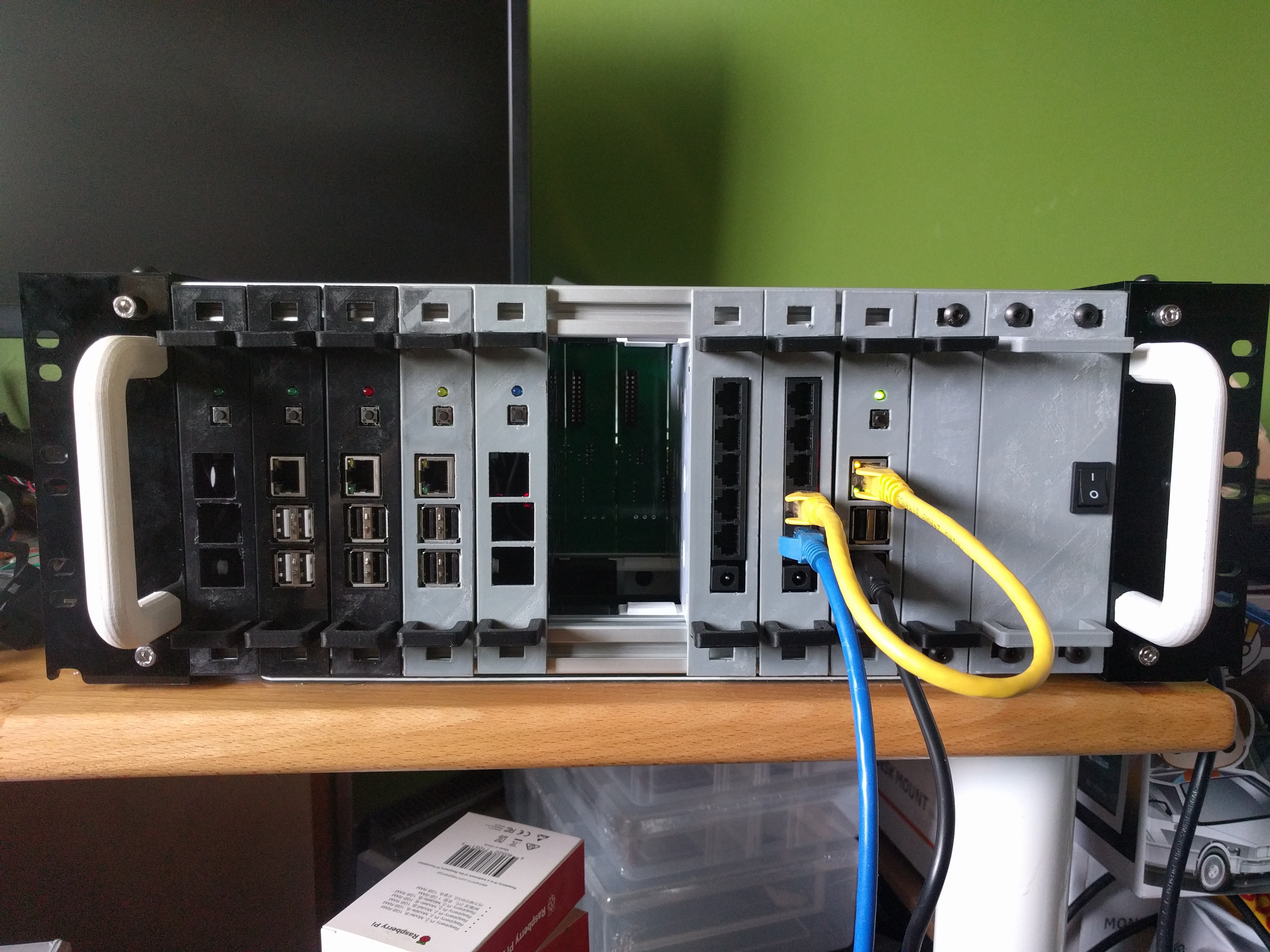
Inspired by thingiverse creator KronBjorn and his 6 inch rack standard. Heavily modified to work with Caddyshack.
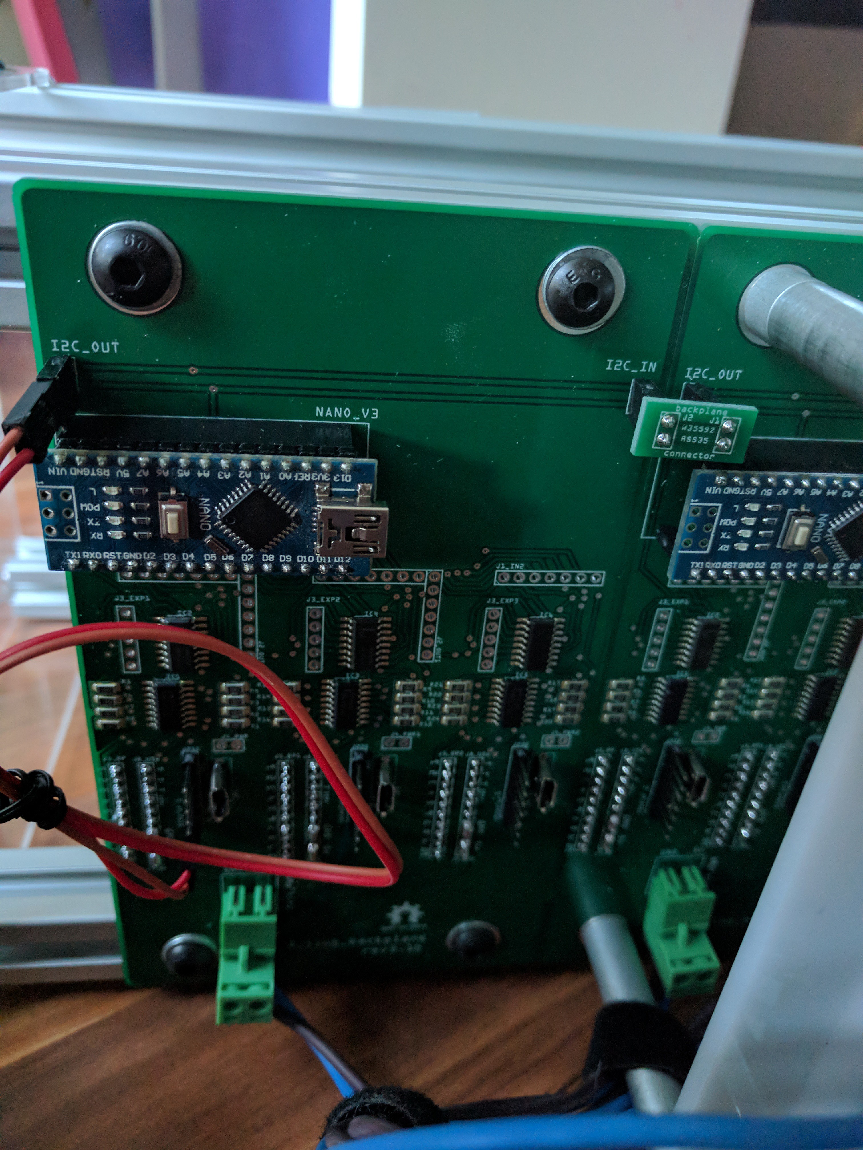
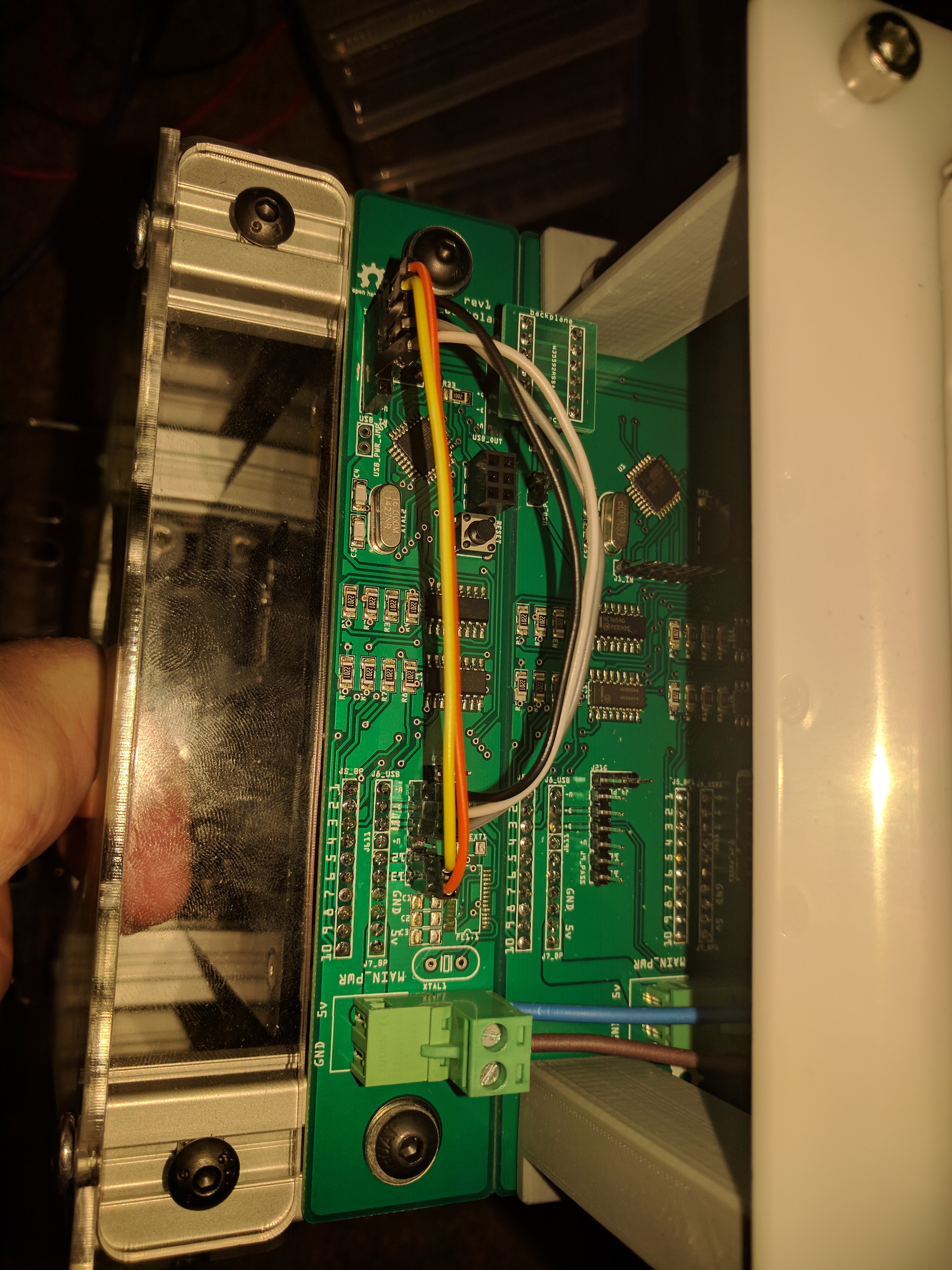 I also have new backplane boards with integrated USB hub and atmega328s onboard 3 slot backplane units.
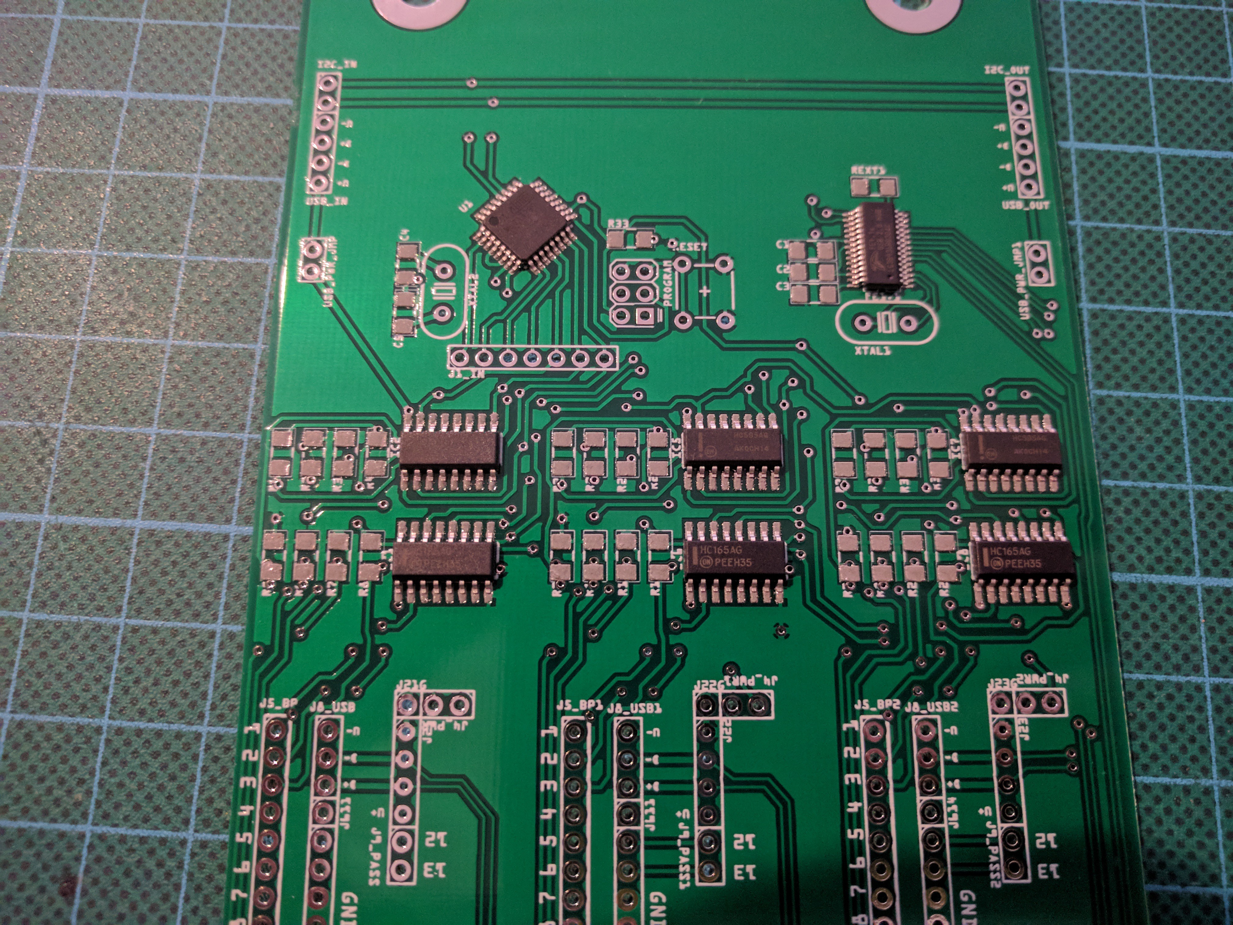


 vileer
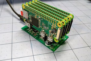
 ajlitt
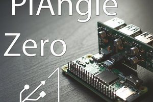
 Sean Hodgins
This is awesome.
I have an old rack mount SAN box my former employer weas getting rid of (management system was a pain in the @$$ to work with and the physical interface was proprietary) that I was allowed to bring home. 16 full size drive bays that should fit a Pi3 easily. Id thought about making it a cluster of Pis but wasnt sure how id tie them all together. The core components of this project look like they would do exactly that with a litle physical tweaking.
The SAN has 16 full size drive bays and a 2x16 LCD module on the front. Each drive bay has a caddy. each caddy has an eject button as well as status LEDs. Redundent power supplies as well as a module for the management card that bolts into the back of the frame (so it wouldnt need to take up one of the 16 drive bays) Im going to need to take a much closer look at your project when I have some more time.