 Robert Gowans
How does it work?
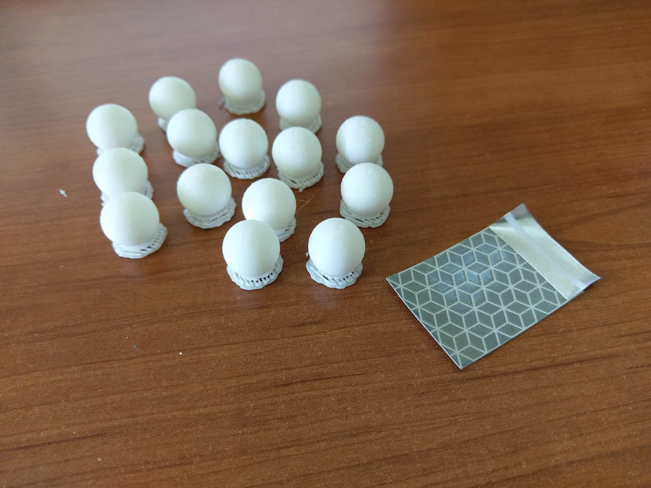
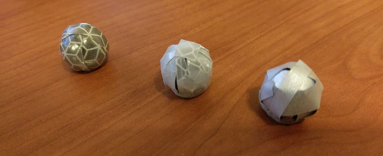
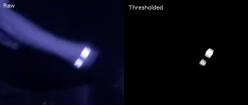
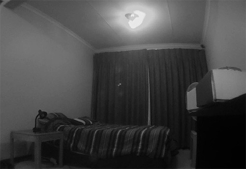
This motion capture system triangulates the 3D position of reflective spherical markers that have been placed in strategic positions on the human actor. It is called an optical system because it uses cameras to 'see' the markers. A typical system will consist of 6 or more cameras. Once the 3D positions of the markers have been recorded they can be used to reconstruct the motion of the actor in a 3D digital space.
There is far more detail on the principles of motion capture online, here is a link to get you started if you're interested: https://en.wikipedia.org/wiki/Motion_capture.
Hardware
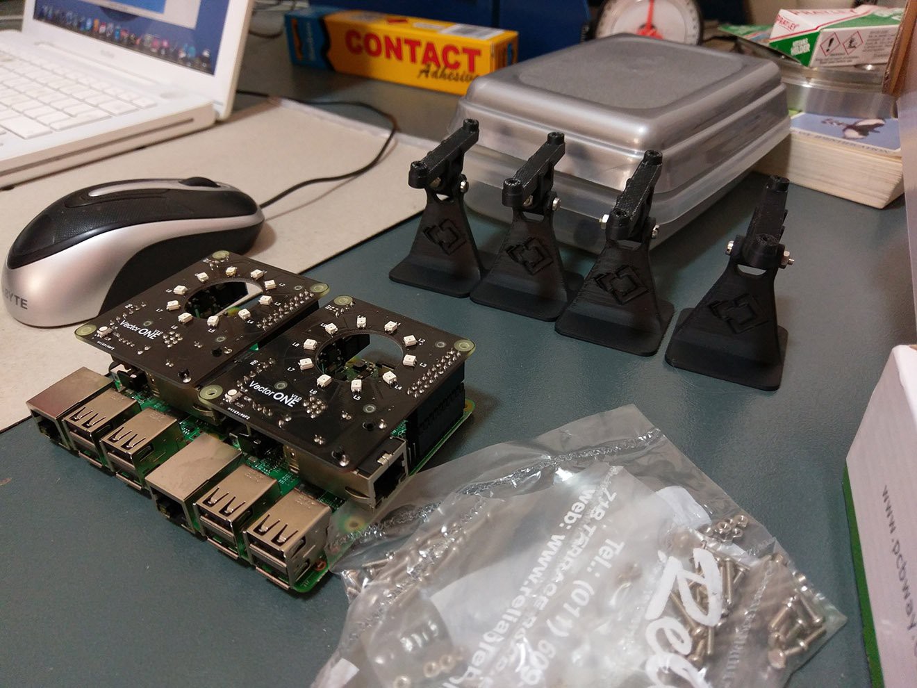
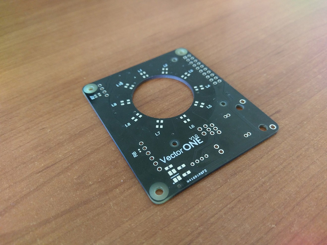
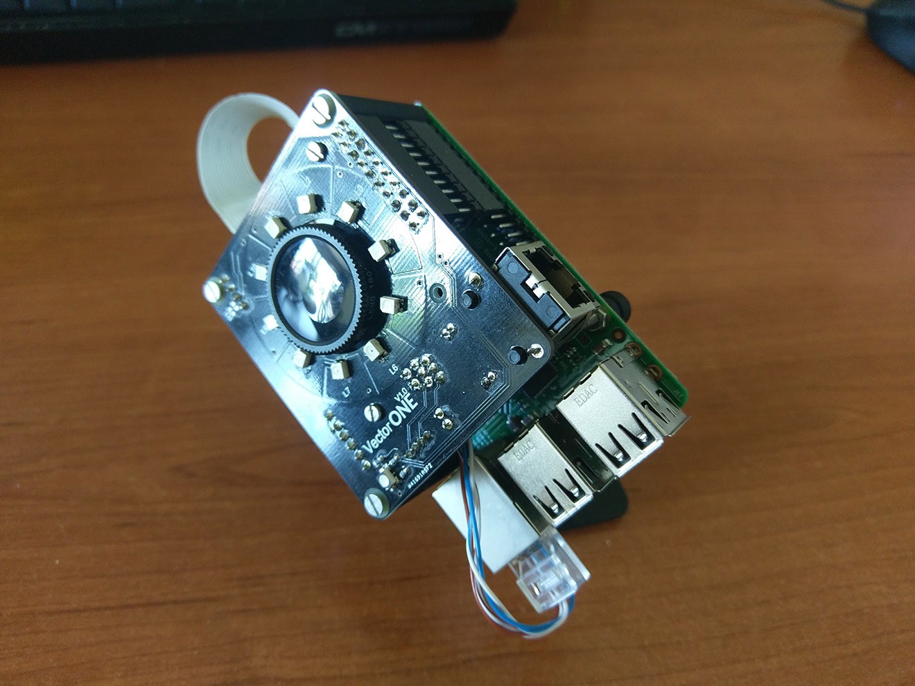
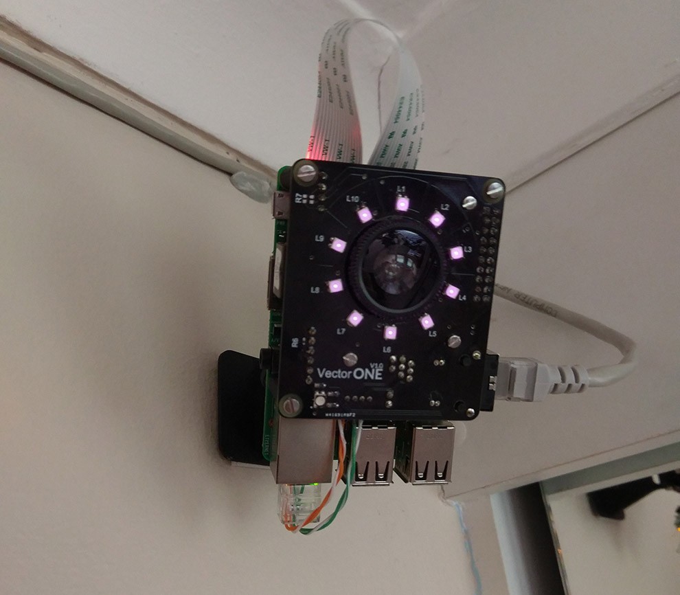
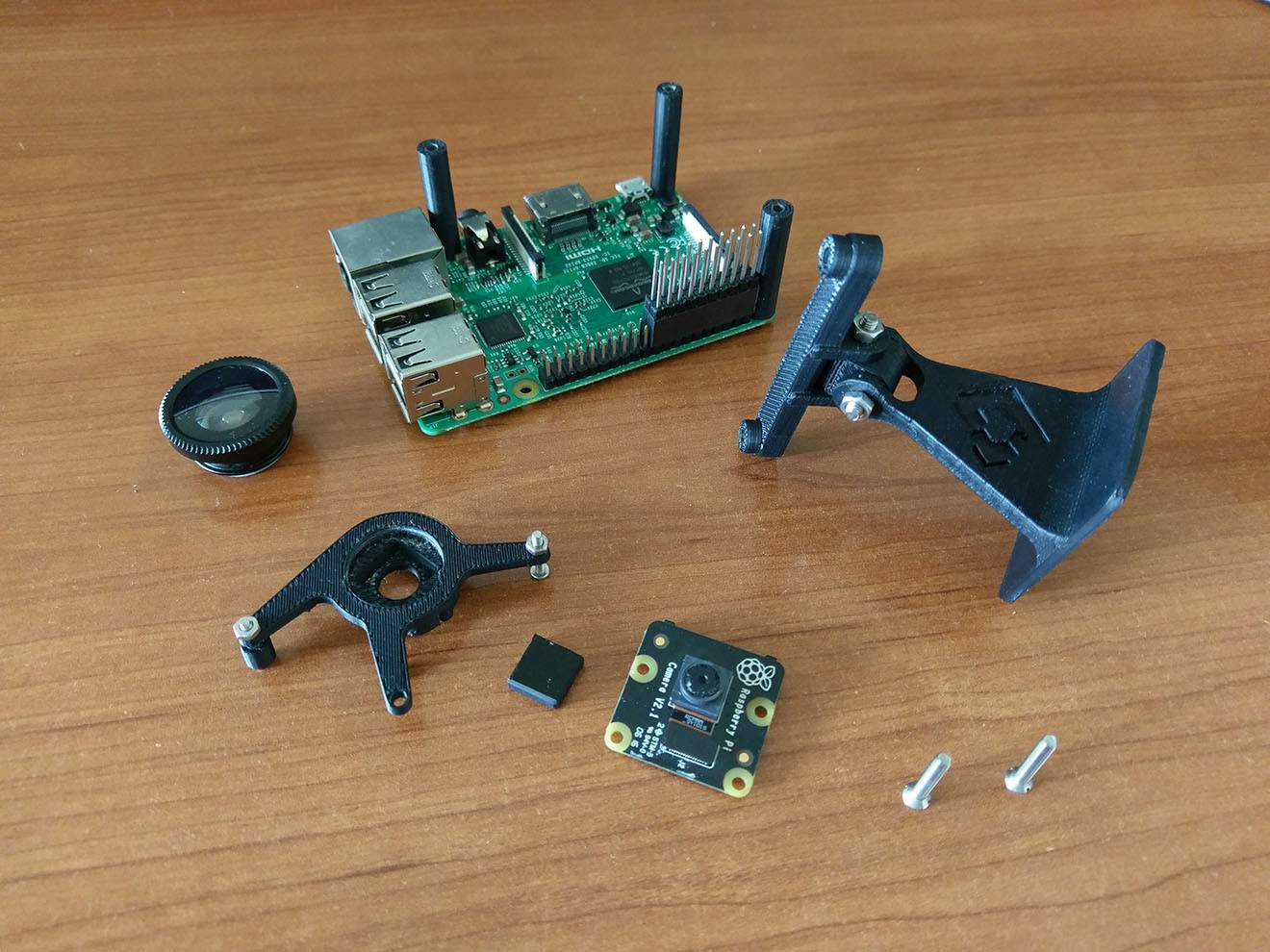
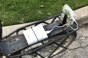
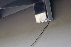
Some capabilities and components of each motion capture camera:
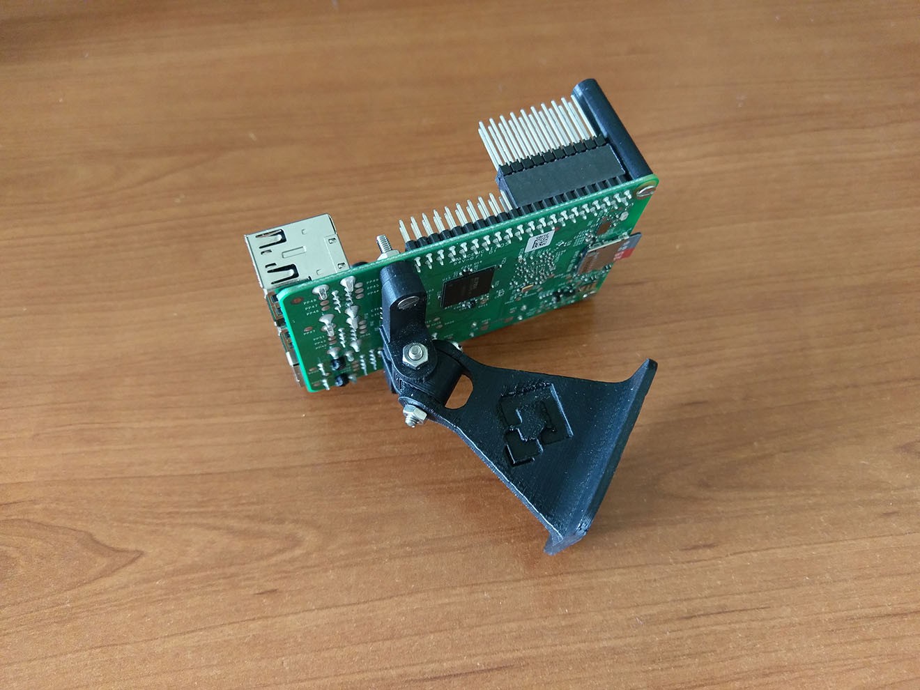
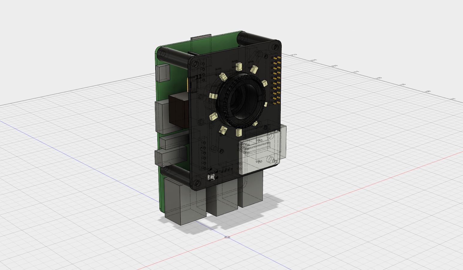
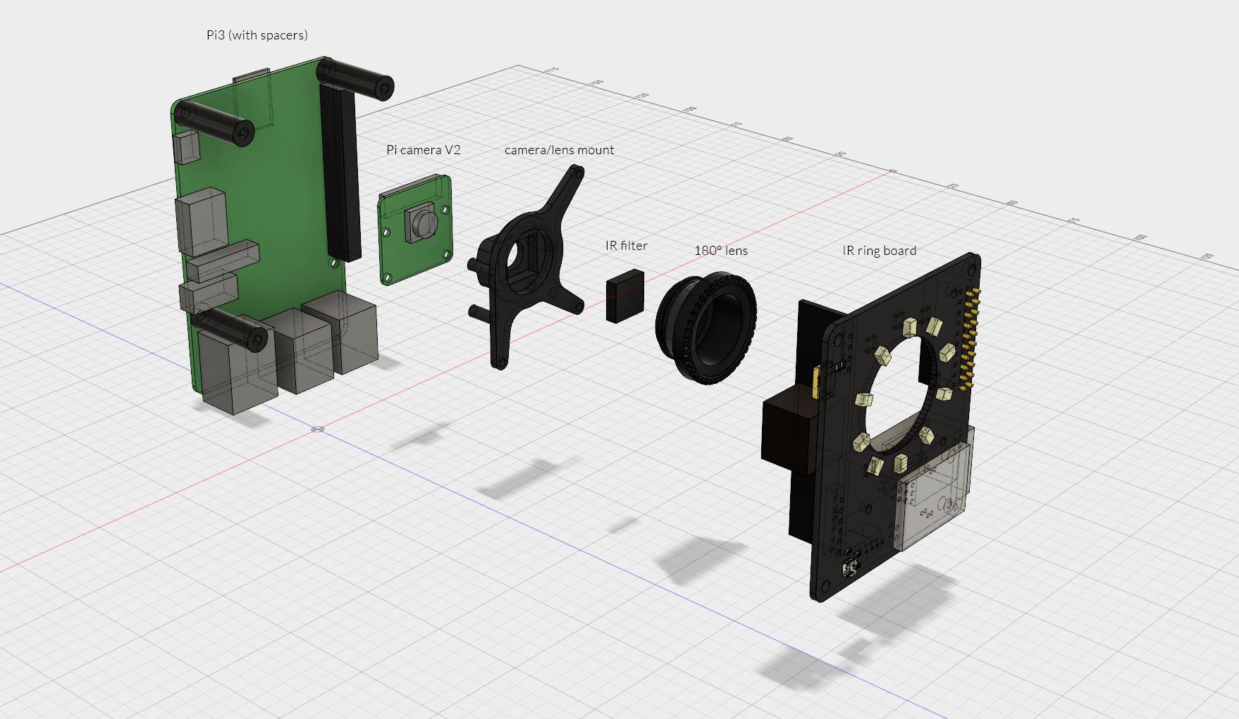
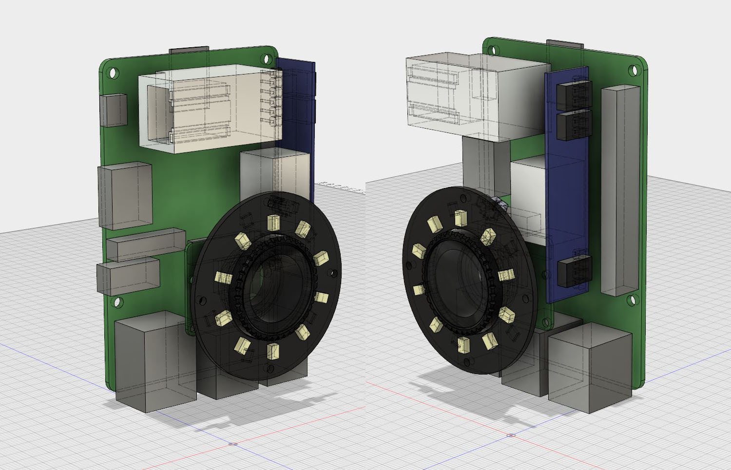
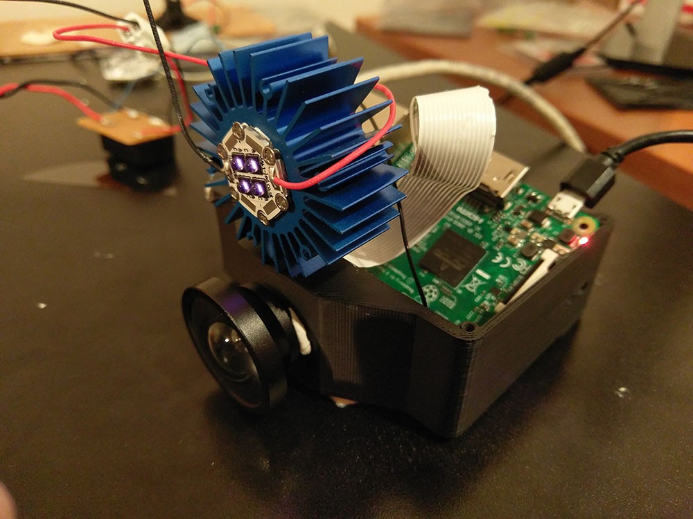
- Raspberry Pi 3
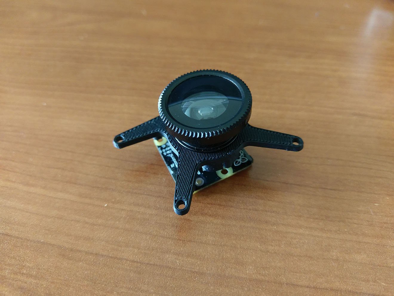
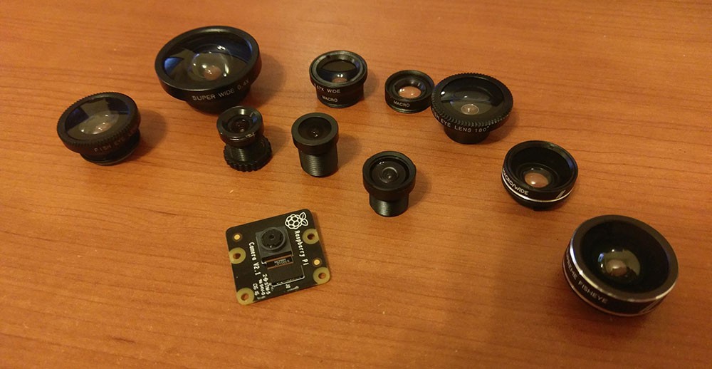
- Pi NOIR V2 camera
- POE (Power-over-Ethernet)
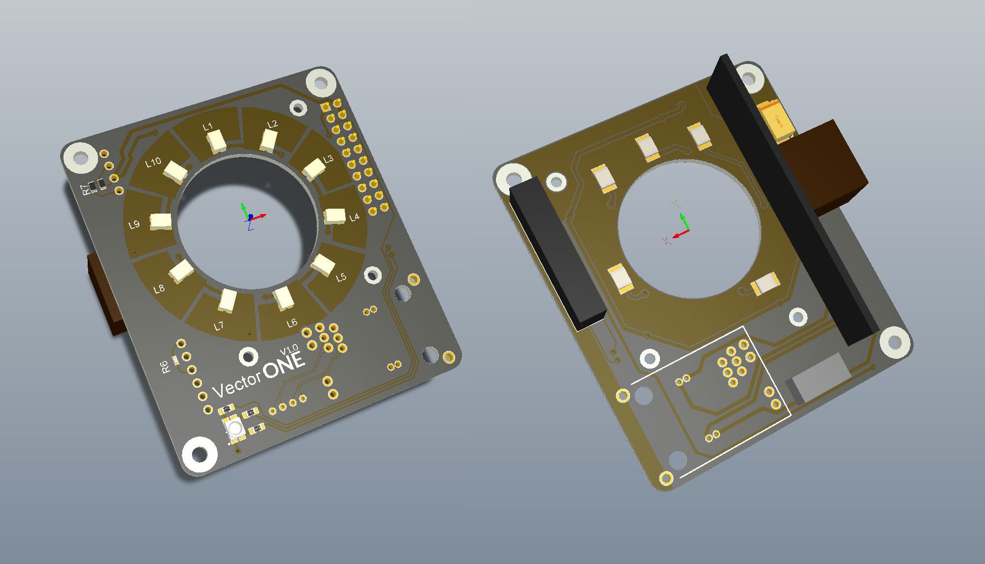
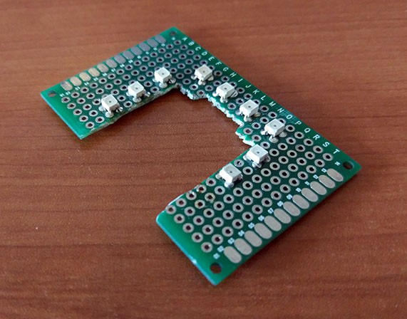
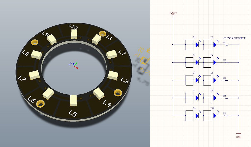
- IR Illumination ring
- Status RGB LED
- On board marker processing
Firmware
Some details of the software that runs on a motion capture camera:
- Communicates with host PC
- Written in Python
- Frame timing and marker processing extensions written in C++
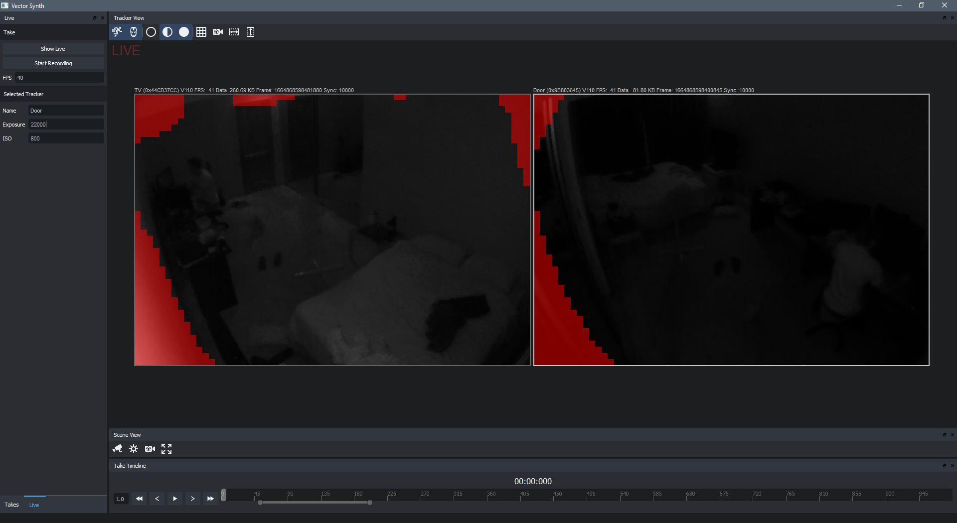
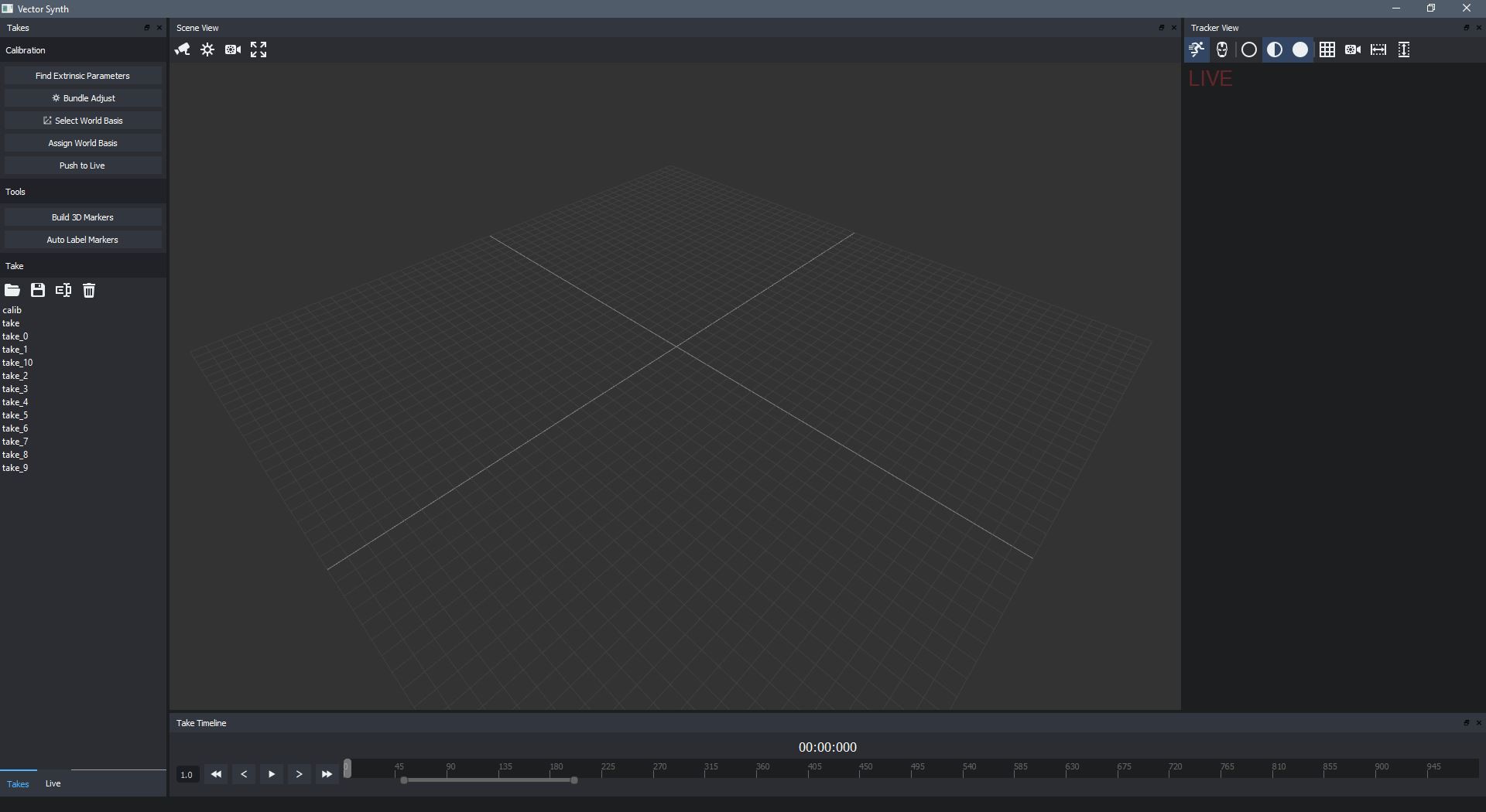
Software
Some capabilities of control software that is run on a single host computer:
- Manages & configures cameras
- Maintains master timing
- Records camera data
- Calibration tools for capture volume
- Triangulates markers
- Identifies markers
- Reconstructs skeletal poses

 J. Peterson
 aleksey.grishchenko
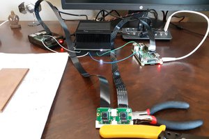
 Nick Bild
Hello
May I ask where you got the IR filter for the camera?
Thanks