 Robert Gowans
Control software
Overview
In my setup I have a dedicated gigabit POE switch that connects 4 cameras and the host PC, of course the switch also supplies power to the cameras. The control software runs on a single PC that is connected to all the cameras on the network and handles tasks such as configuring cameras, managing recordings and triangulating markers.
I decided to use the Qt framework with C++ as the primary platform for writing the software. I always tend to favour Qt when it comes to interface heavy projects and there is a nice bonus that it has many useful libraries such as network communication, threading and image manipulation.
Live mode
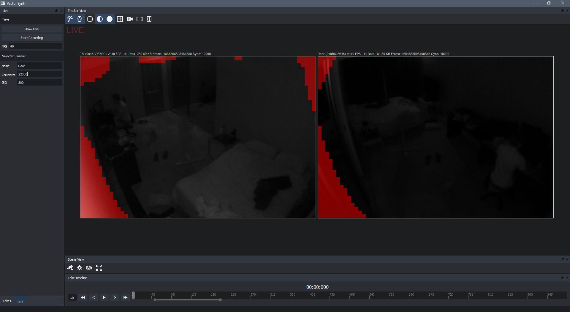
There are two modes in the software: Live and Take. Live mode lets you view the currently connected cameras and initiate recordings, while Take mode lets you go over and process previous recordings. There is a constant ping broadcast from the host PC that allows any cameras on the network to locate the host software and make a connection. You can see in the above screenshot I have two cameras hooked up and each is in video mode. Video mode allows a constant real-time video feed from the cameras so you can see exactly what the camera sees. However this is purely for setup convenience as when recording the cameras won't broadcast the full video frames, but rather just the marker positions.
The video feed coming from the cameras is almost completely latency free and when running at 100fps the result is ungodly smooth. As mentioned above you don't actually use the raw feed in recordings, but it was an interesting experiment to gather and broadcast the frames anyway. I used the FFMPEG library to handle the h264 encoded video that was being sent from the Pi.
The red blocks you see on the video feed is manually placed masking. There will inevitably be some areas in the video that are bright enough to be considered markers, so masking tells the camera to just ignore that area completely. Typically you will mask out the IR reflections on walls close to the camera and also IR LEDs from other cameras.
Take mode
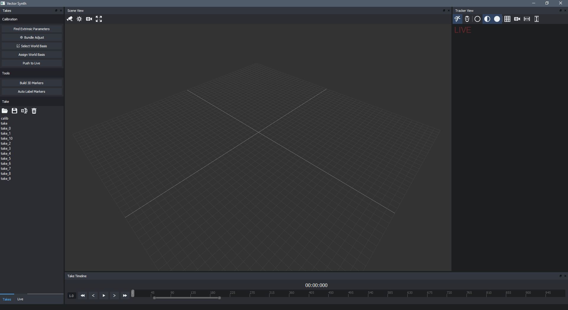
Take mode lets you view and process previous recordings. I have used OpenGL to drive the 3D viewport where hopefully finally triangulated marker positions will end up. The timeline allows you to scrub through all frames in a recording, as well as selecting a time range to perform various operations.
Camera firmware
I decided to write the software running on the Pi (which I will refer to as the firmware) in Python. Primarily this was because the excellent picamera is a Python library. Picamera gives you advanced access to Pi camera functionality and makes it very quick and easy to get a camera project running.
Of course Python is not capable of processing data in an image at any reasonable speed, and on the Pi Python is painfully slow. Luckily it is very easy to write and integrate native C code into Python modules. In a further log entry I will discuss the marker processing which was written as native C integrated with Python.
Discussions
Become a Hackaday.io Member
Create an account to leave a comment. Already have an account? Log In.
I working also on a camera based mocap solution and i search for a software solution that not so expensive. I work with 1080p 60fps camcorder with infrared mode. i have decided against the rasperry pi cameras because they only have 30fps at the 1080p resolution. Is the software programmed by yourself? Maybe we can exchange experiences and tips. Basically it would be best to control all cameras live from one software. Alternatively I could also record videos and then try to match all points in a 3d tracking software. But that would be very time-consuming.
Are you sure? yes | no