 Yoshitaka Kuwata
piggybackLED
7x5 LED Matrix display with 3 parts
1. Introduction
Piggyback LED is simple LED Matrix driver. This can be use as badge which display messaes and patterns. The idea of this project is based on a concept I called ‘Piggyback-computing’ which is just connect components on a CPU in piggyback style.
2. Components
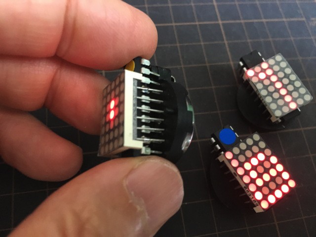
You need one attiny2313 (DIP package), one 5x7 LED matrix module(18mm or .7inch) , and one coin battery cell (CR2032).
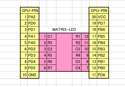
The most important factor of ‘piggyback computing’ is pin assignments of CPU and other components, in this case LED matrix.
AVR is selected because it can drive LED directly. attiny2313 is selected because VCC and GND are assigned on the edges of the chip and I get 6 freely programmable pins on the both side of the chip.
3. Piggyback Connection
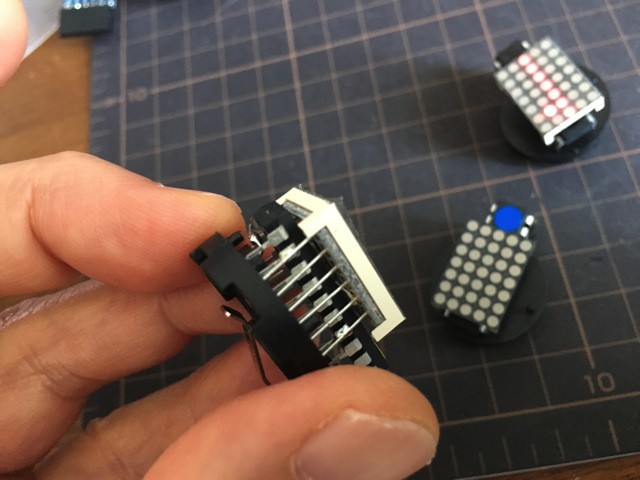
Just put LED-matrix module on attiny2313. Please note the alignment of CPU and LED pins. No soldering is necessary for tests.
4. Software
Customize ‘matrix.c’ to display what you want.
Makefile is used to compile the codes. You need to pre-program attiny2313 before connecting LED-matrix module.
In order to turn LED on, you need to connect VCC and GND to coin cell battery.
That’s it.
Note the software is hosted by github
https://github.com/kuwatay/piggybackLED
Demonstration video


 Nicholas Stedman
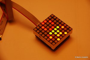
 Martin Hub
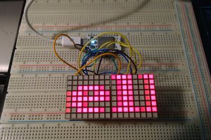
 Pierre Cauchois
 Brenda Armour
Hi, davedarko
Thank you for your comment.
Actually, I inspired by arms22 at http://arms22.blog91.fc2.com/?tag=Dotsduino , which is 8x8 matrix led based on mega328, Arduino. I'v designed 7seg4digit LED module built with mega328, which is named 7segduino. http://morecatlab.akiba.coocan.jp/lab/index.php/aruino/7segduino/ .
I'm surprised someone had already implemented something similar.