This is a little circuit that could be used to track an object up to 400m.
It is a SAW stabilized OOK modulated RF transmitter, the modulation is done with two low frequency ultra low power oscillators that activate the transmitter every two seconds for a short period.
With the setup shown here I got up to 400m range. Current consumption is about 180uA average so it'll work for a couple of days with the little button cell (364 / SR621SW). Frequency 915MHz.
On the schematic, the first oscillator to the left activates the second to its right every 2 seconds or so. The second oscillates at about 800 to 900Hz. Its output signal modulates the RF transmitter which is essentially just a SAW based oscillator with some of the RF energy coupled to a whip antenna.
The adjustment of the RF oscillator can be tricky but works fine with the components shown. The jumper resistor over the SAW element allows the frequency to be adjusted near the SAW fundamental frequency, then the jumper is removed and the circuit will oscillate at the SAW frequency.
The lower you go in frequency the easier this adjustment will be, so you could go for 433MHz for example too. The component to be changed would be the inductor then (about 22nH).
Use NPO caps for the RF area. The type of the inductor is not critical, I used ceramic.
The circuit would actually benefit from a buffer stage or a matched antenna output, but frankly I didn't feel like investing more time in it. :-)
Building it requires a hotplate and solder paste or a soldering iron with a fine tip and steady hands.
Make your own PCB layout or download mine from here: Google drive link
Upload the .brd file to your favourite cheap PCB manufacturer, I used Oshpark.com, will take two to three weeks and then:
1. Put solder paste on every pad a component will be placed on
2. Place all components
3. Heat the entire board on a hotplate and wait until the solder paste liquifies
4. Remove the board form the hotplate , let it cool down
5. Flip the board around and solder the battery holder on it
6. Solder the antenna wire into the hole
7. Important: Put some conformal coating or silicon etc on the component side. This will protect the circuit from contamination and humidity. The LF oscillators use pretty high resistance values, which means they are easily detuned if for example you put your finger on it.
Step 3: Range and Stability
The RF frequency is SAW stabilized so shouldn't drift. I did not test the circuit in extrem conditions, but it worked fine from room temp to minus 15C.
Range was about 400m line-of-sight ( does that make sense in this case? :-) )
You can play around with the antenna length and also try to increase the ground area adding some conductive material to the GND pin of the battery holder for example. The short green wire increased the range in my case.
The receiver is comprised of a YAGI antenna, an adjustable attenuator and a RTL-SDR receiver.
The RTL-SDR dongle is connected to a cellphone that runs a paid app called RF analyzer. It's not expensive.
If you mount the antenna on a car for example the dongle could be connected to a Windows PC though, and there is free software available for Windows.
The YAGI antenna design came form here: https://273k.net/gsm/designing-and-building-a-gsm-antenna/yagi/
There are many other designs on the net and you could also buy an antenna.
The RTL-SDR dongle comes from here: https://www.rtl-sdr.com/buy-rtl-sdr-dvb-t-dongles/
It's an incredible versatile and very useful gadget for the occasional RF Hobbyist, AND its price is unbeatable.
The attenuator is made of a shielded box with three DPDT switches and attenuates 10dB for each stage. Use small resistors and short connections. Its performance at these high frequencies I didn't feel like evaluating but it attenuates a good amount and that's all that counts. I didn't use any particular website for this part so you have to look this up for yourself. Search for How-Tos of RF attenuators...
Read more »


 Alpenglow Industries
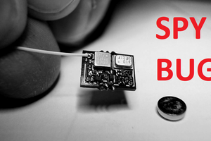
 Lithium ION
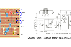
 agp.cooper
is it possible to increase the range keeping this size?