Close
0%
0%

Wall Following and Obstacle Avoidance

Raspberry Pi 3B based robot, distance sensors, and ROS.

Similar projects worth following

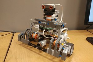
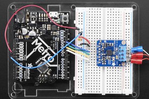
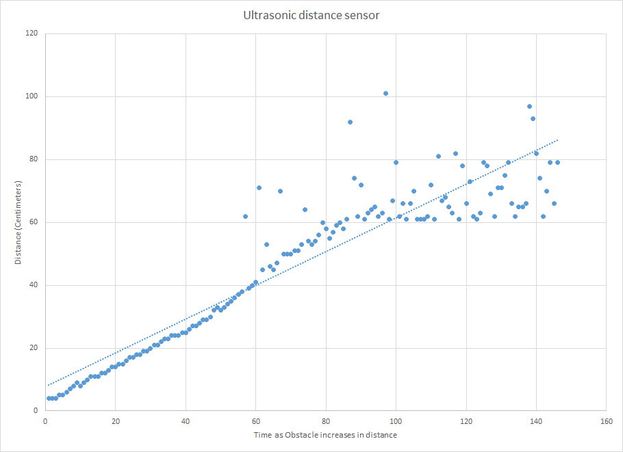
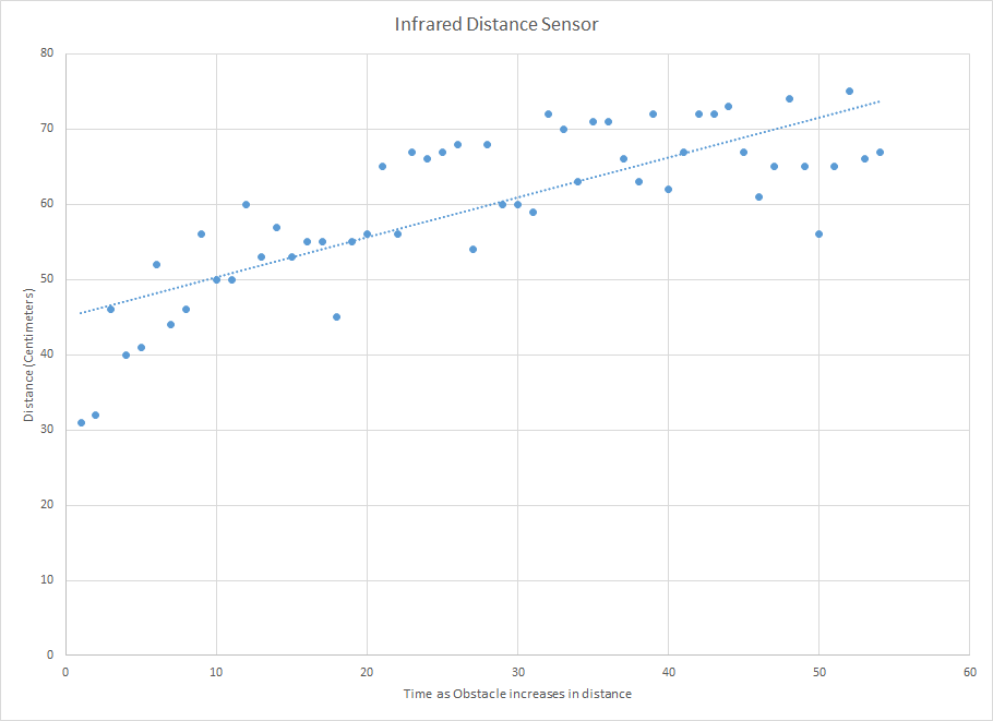
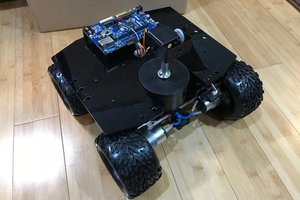
A raspberry pi based robot AKA Shaky that can detect obstacles and navigate around them. It is meant to follow walls. It uses three ultrasonic distance sensors and two infrared distance sensors. An Arduino Uno manages the sensor reading, Robot Operating System (ROS) handles the control system. 

Wall_Following_Output.txt

Output of ROS program

plain - 13.24 kB - 12/22/2017 at 07:08

Download

wall_follow.py

Main program for Reference

py - 4.83 kB - 12/22/2017 at 07:08

Download

Wall_Follower_Sensor_Node.ino

Arduino program for Reference

ino - 3.04 kB - 12/22/2017 at 07:08

Download

Crash.mp4

Crash and Burn

MPEG-4 Video - 18.74 MB - 12/22/2017 at 06:11

Download

Uturn.mp4

Turn in a U shaped environment

MPEG-4 Video - 15.97 MB - 12/22/2017 at 06:10

Download

View all 9 files

  • 1 × Raspberry Pi 3B
  • 2 × Motor and Wheel
  • 1 × Motor Driver Hat
  • 1 × Arduino Uno
  • 1 × Ultrasonic Distance Sensor (3-400cm)

View all 7 components

  • Conclusion

    Sinclair Gurny12/22/2017 at 07:07 0 comments

    Thoughts

    Overall, Shaky is able to follow walls with some degree of accuracy as well as avoid obstacles. Shaky has some problems turning and that causes some issue with getting stuck next to walls. And the sensor refresh rate and motor controlling causes a overall jerky (shaky) robot, due to the smell steps between each sensor reading. The original design and algorithm called for the use of two distance sensors on each side to estimate the relative orientation with a wall and correct it to stay parallel. However, this was not feasible due to the inaccuracy of the sensors and limits on controllability of the duckiebot. Furthermore, the method in which the sensor values are read limits the refresh rate of the sensor data. Redesigning the code would fix this issue, where one ROS node reads the value and another ROS node runs the algorithm. This would be the next problem addressed when I continue to work on this project. The system has many constant values for speed, time, and distance. Each of which needs to be tuned to allow the system to work effectively. The method used to tune the values was trial and error. The robot was placed in a location where the algorithm will reach the part in the code where the values you want to tune are being used. Then according to the error in the behavior during the test you adjust the values higher or lower. The system outputs the current action (i.e. following left wall, turning around) being performed along with a timestamp so the actions can be deciphered by looking at the output of the system. One source of error is that because of the center of gravity due to the battery, Arduino and sensors, as well as the traction and torque of the wheels the robot has a hard time performing turns especially with small radii.

    Improvements

    The first place for improvement is in the code. Fully designing a launch file, nodes for sensor reading, algorithm running, and performing motor actions. Furthermore, another big issue is the sensors. The inaccuracy of the IR sensors makes accurate wall following nearly impossible. Replacing the IR sensors with more Sonar sensors will fix this problem. Adding even more than five total sensors will allow for higher resolution of navigation. However, interference is possible if multiple sensors are going to be ran at the same time. The issues with turning and driving straight are not critical and could potentially be fixed using encoders on the wheels. Also trying to balance the weight distribution would improve Shaky's ability to drive. 

  • Sensor Testing

    Sinclair Gurny12/22/2017 at 06:46 0 comments


    Sensor Accuracy Test

    I performed a test of sensor accuracy and precision. The test placed the sensor on the stationary robot. A reference object, a large flat object, was placed in front of the sensor and slowly moved away from the sensor at a nearly constant rate. The sensor values were recorded and graphed. A linear trendline and R^2 values were calculated to measure the accuracy. This test shows the error in measuring the distance and the accurate range of each sensor.

    The results show that the sonar sensor (Figure 1) was nearly perfectly accurate up to a distance of 60 cm. After 60 cm the error rate increased, possibly due to several reasons: receiving some interference from the environment or the sensor was receiving pulses that bounced off of things other than the reference object. The trendline equation y=0.5376*x+7.688, and the R^2 value was 0.855 which shows a fairly accurate sensor overall. 

    Figure 2 shows the accuracy of the IR sensors, which is much worse than the sonar sensor. Low end values were not read accurately the minimum was much higher than the supposed minimum of 10 cm, and the error is very large taking into account the smaller range which the IR sensor works in. The trendline equation is y=0.5311*x+45.061 and the R^2 is 0.6259, which shows less accuracy than the sonar sensor.

  • Software

    Sinclair Gurny12/22/2017 at 06:39 0 comments

    Software

    Shaky uses python and ROS to handle the logic of the program. The values from the Arduino are read using the pyserial python library. The control algorithm consists of two modes: picking behavior and following a wall. In the picking behavior mode the robot decides which action to take given all the different combinations of walls. For example: turn around if in a dead end, turn out of a corner, drive straight if no walls are detected, and choosing a wall to follow. Wall following mode consists of keeping the correct distance with a wall and switching back if obstacles are detected.

  • Hardware

    Sinclair Gurny12/22/2017 at 06:35 0 comments

    Robot

    The robot is a duckiebot from Duckietown. The base is a Raspberry Pi 3B with a motor hat to control the wheel motors. It is powered by a power bank. The sensors interface with an Arduino Uno. The Arduino reads the sensor values and outputs the values in the form: "[S1 S2 S3 S3 IR2 IR3]\n". S are sonar sensors, IR are infrared sensors. 1,2,3 are the directions front, left, and right respectively. The values are outputted via Serial. The Raspberry Pi connects to the Arudino via USB.

  • Sensors

    Sinclair Gurny12/22/2017 at 06:24 0 comments

    Ultrasonic Sensor

    AKA Sonar Sensors measure distance by sending a sound pulse and waiting for it to return. The datasheet lists accuracy up to 400 cm in ideal conditions. Sonar sensors are digital sensors that require two GPIO pins to use: one to ‘Trigger’ the ultrasonic pulse, and one to receive the time for the ‘Echo’ to return. The distance needs to be manually calculated using the time it takes for the echo pin to return a pulse, and the speed of sound. The equation becomes distance = ((time / 29) / 2). Where time is in microseconds, 29 microseconds per centimeter which is the inverse of the speed of sound in the correct units. Half of that distance is taken because the pulse goes there and back.

    Infrared Sensor

    Sharp IR distance sensors measure distance by sending IR light and measuring the angle at which it returns. IR sensors are analog, which lead to several design choices discussed later. The sensor can measure distances between 10 cm and 80 cm, by reading voltages of  3.1V and 0.4V respectively. However, according to the datasheet and as seen in practice the actual voltages can vary.

View all 5 project logs

Enjoy this project?

Share

Discussions

Similar Projects

Does this project spark your interest?

Become a member to follow this project and never miss any updates