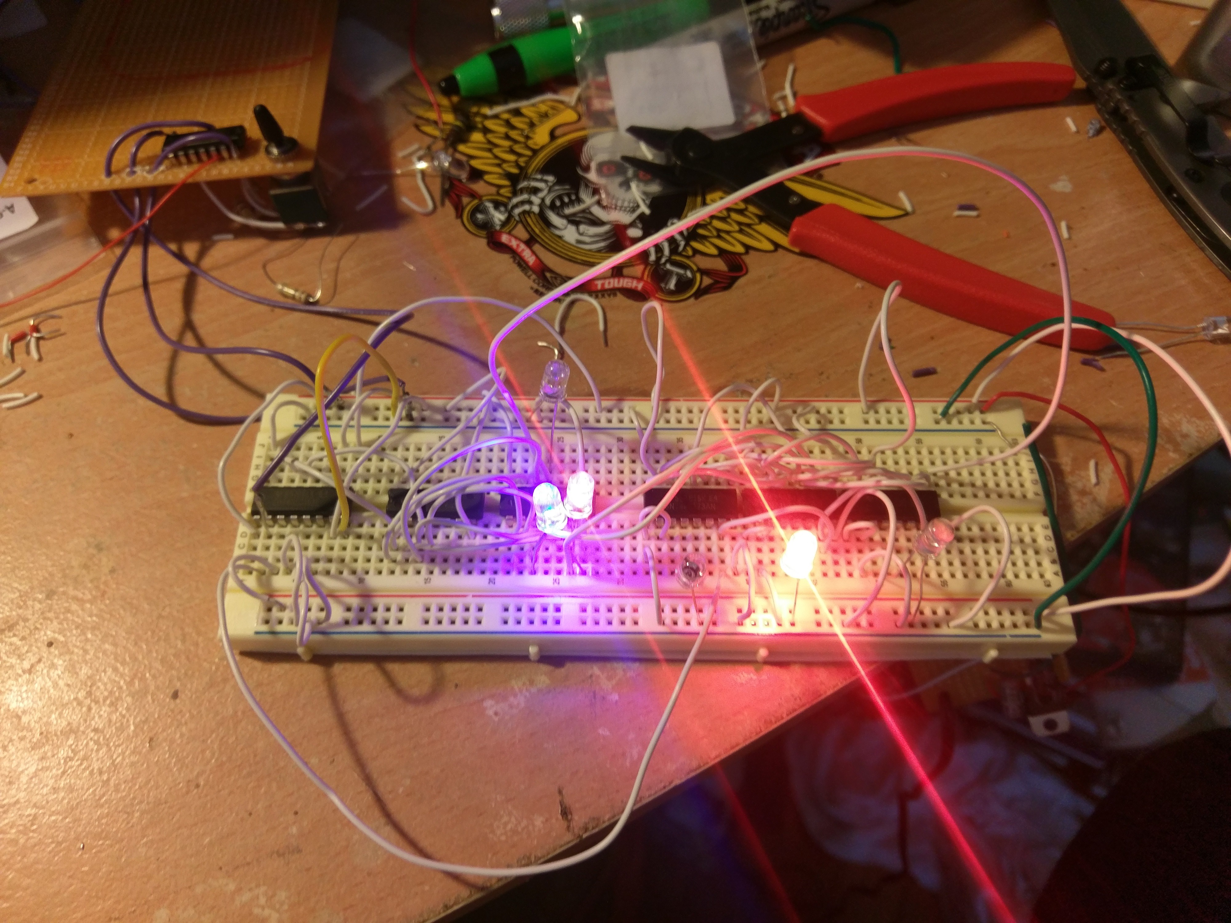
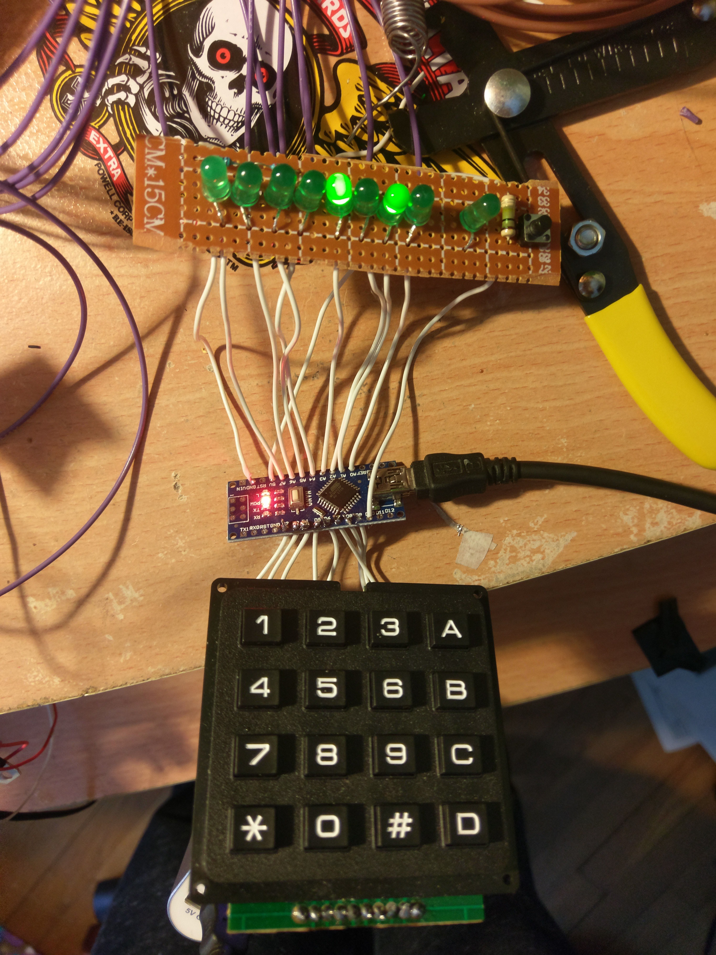
• The 12-Bit Register

    Boxerbomb01/15/2018 at 19:17 0 comments

    The Boxer-1 uses instructions that look like:

    [4-bit Opcode]    [8-bit Data]

    Registers A and B are each 8-bits. These are general purpose registers that are used for the Adder/Subtractor as well as general writing and reading to ram. They only effect the 8-bit data space.

    Register C is 12 bits long. This allows for entry of opcodes into ram. This register is put into effect by using a 4-bit Binary Counter, an Inverter, and a Nand gate to create a ring counter. I ended up using these chips just because they are available. Data is entered 4-bits at a time to the register. Three "Load C" instructions complete the write. 

    I am still learning about computer architecture and from what I understand having a 12-bit register on an 8-bit computer is unusual. To the best of my knowledge it is the best way to take full advantage of the 8-bit address bus. 

    Attached is my first attempt at building this register. It still uses a single step clock source so I have no idea how to will preform at a higher clock rate. I might have to add a falling edge clock circuit.

  • Hex Keypad Entry

    Boxerbomb12/29/2017 at 18:09 0 comments

    I have created a hex Keypad entry system using Arduino. The Arduino decodes the keypad with the matrix library and provides a binary output. The keypad currently isn't tri-state but I will add a fix either in the code or by adding a 74ls245. I use it just for easy testing of the system but will be later used by the user with clock interrupts. 

  • 8-bit Adder

    Boxerbomb12/21/2017 at 19:39 0 comments

    The first part of the project is complete. It includes an an A-Register, B-register, and an 8-bit adder. There is also an overflow bit and there is room on the board to use AND gates to create an equal bit. The bits will be used to control conditional jump statements later in programming. The equal check is essential to create my hex editor program later on.